You can place an online order for a 3D print with 3Faktur. You can find instructions here.
On this page you will find technical information about your order, with a focus on hollowing out solid structures, the support surface for vapor smoothing and general information about internal channels in components.
For further information, please also visit the following pages:
Minimal design requirements: These include, for example, minimum wall thicknesses. Details can be found on the respective material pages. To the material overview
More detailed design requirements: Information on special functionalities and optimization strategies for additive manufacturing can be found here: Construction and design information for additive manufacturing
Option: Allow Hollowing
Background
In solid PA-12 components with wall thicknesses ≥ 6 mm, excessive heat can build up inside during the Multi Jet Fusion process. The consequences are:
Increased inaccuracy – uneven shrinkage leads to dimensional deviations.
Warping – temperature gradients create internal stresses.
Surface defects – “elephant skin” (grooves) or yellowish discoloration caused by powder oxidation.
Reduced strength – heavily oxidized raw material reduces mechanical performance.


Recommended Option
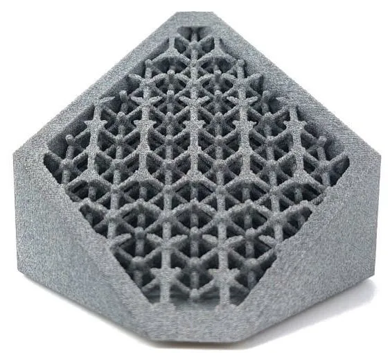
When selecting “Allow hollowing”, we remove the solid material inside the component and insert a lattice structure (grid), which is enclosed by a solid outer shell.
Wall thicknesses
- Classic: approx. 3 mm
- Essential | Performance | Smooth | White: approx. 2 mm
Inside, compacted, unfused PA-12 powder remains. This design reliably prevents the effects mentioned in the background section – dimensional deviations, warping, “elephant skin”, or loss of strength.
For the Classic and Performance variants, we can also produce your component as a solid body. However, by selecting this option, you accept the quality risks mentioned above.
In the quotation and ordering process under “Configure components”, you will find the available options. The integration of hollowing or lattice structures is carried out by us at no additional cost.
Support Surface for Vapor Smoothing
Background
In the chemical smoothing process (“Vapor Smoothing”), the surface is temporarily liquefied by evaporated solvent (a few µm). This process creates a largely pore-free and smooth surface. The liquefaction leaves visible marks on the component. You can find general backgrounds, guidelines, and information about the technology on our page: Vapor Smoothing (Chemical Smoothing).
Your Options There are two options for handling the component in the process:
- Option “Placing”: The component is placed on a “nail bed” or grid, resulting in point- or line-shaped impressions. The support side (bottom) is less processed in the process, while the smoothing mainly occurs on the opposite side of the component (top). This option is more cost-effective and recommended for components with a clear visible side and a “non-visible side.” This is the case for most housing parts, for example. You can optionally upload a drawing (PDF format) specifying the visible side.
- Option “Hanging”: The component is suspended from a hook, resulting in only one impression at the hanging point. As a result, the component is smoothed more evenly from all sides. Since this is more complex in the process and the relative space requirement per component significantly increases, this option is more expensive. Please note that with the “Hanging” option, a structure must be present in the component on which it can be hung. These can be blind holes, breakthroughs, or loops, for example.
In the quotation and ordering process under “Configure Components,” you will find the available options. You can optionally upload a technical drawing specifying the support or hanging surface.


Internal Channels & Undercuts
Background
During the printing process, the powder is compacted (“pressed”) at high temperatures. Increased process temperatures occur at internal channels and undercuts because the heat is trapped locally. As a result, the previously loose powder is lightly sintered and becomes very solid in the corresponding areas.
Your Options
The residues are removed by glass bead blasting. Access to the areas is necessary for this. If access is not possible, powder residues may remain in these areas and, for example, clog channels. This can only be avoided by making design changes to the component. You can find suggestions for design optimization for additive manufacturing here.

Example internal channels. This component includes additional structures that facilitate cleaning of the channels. Learn more in our design guidelines for channels.
Questions?
If you have any uncertainties in the ordering process, questions about your quote, or technical inquiries, our customer service is available to assist you!
Office Hours
Monday – Thursday 08:00 – 16:00
Friday: 08:00 – 14:00
Contact
Phone: +49 3641 225910-20
Email: angebote@3faktur.com
