How the instant quote works
From 3D file to order in just a few steps.
01
Upload 3D file
Upload your part as an STL or STEP file. Multiple parts can be calculated together in one project.
02
Configure your part
Select the process, material, quantity, and the manufacturing and post-processing options available for your part.
03
Get price & lead time
The price and expected shipping date are calculated instantly. You can also download a PDF quotation.
04
Order online
Add the configured parts to your cart and complete your order online.
3D printing processes available for instant quoting
Depending on the application, different processes, materials and configuration options are available.
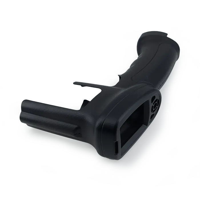
MJF – Multi Jet Fusion
For high-quality polymer parts, complex geometries and industrial applications.
PA 12 · PA 11 · TPU
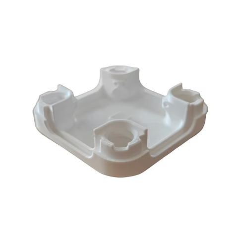
FDM – Fused Deposition Modeling
For fast, cost-effective prototypes and functional parts with simple to moderately complex geometries.
ABS · ASA · PLA · PETG
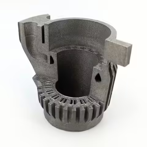
LPBF – Metal 3D Printing
For highly loaded metal parts with complex geometries and demanding functional requirements.
Aluminium · Stainless steel 1.4404
MJF – Multi Jet Fusion
For high-quality polymer parts, complex geometries and industrial applications.
MJF is an industrial 3D printing process for high-quality functional parts, low-volume production and series production. The process provides high dimensional accuracy and repeatability, uniform surfaces and near-isotropic mechanical properties. This results in durable parts whose strength is significantly less dependent on build orientation than with many layer-based manufacturing processes. High-performance engineering polymers such as PA 12 and PA 11 make MJF particularly suitable for permanently used functional parts and demanding industrial applications. At the same time, the support-free powder-bed process enables complex geometries, undercuts and integrated functions.
Which material is right for your part?
The following overview will help you make an initial selection. Technical properties and detailed information can be found on the respective material pages.
PA 12
PA 12 is our most versatile polymer for industrial applications. Several variants are available in the instant quote, optimized for cost efficiency, surface quality or mechanical performance depending on your requirements.
PA 12 | EssentialCost-optimized for economical prototypes and production runs.
PA 12 | ClassicThe versatile standard for a broad range of industrial applications.
PA 12 | SmoothFor particularly uniform, high-quality surfaces.
PA 12 | PerformanceFor demanding functional parts with higher mechanical requirements.
PA 12 | WhiteWhite base material for white and color-dyed parts.
Online-configurable options
Material, color & production time
- Material-dependent color selection (Colors for PA 12 | White)
- Production time
- Standard: from 6 business days
- Priority: from 4 business days (surcharge applies)
- Flex: from 12 business days (discount applies)
- Quantity and shipping date calculated instantly
Surface finish & assembly
- Chemical smoothing (Vapor Smoothing)
- Vibratory finishing (More info)
- Thread cutting and threaded inserts
Quality & technical options
Important technical options
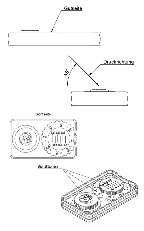
Specify part orientation
Part orientation within the build chamber has a significant impact on dimensional accuracy, surface quality and, for delicate structures, mechanical stability.
By default, we orient each part according to its geometry, material and material variant. For repeat orders, we reuse the orientation from previous production runs wherever possible. This makes orientation an important factor in achieving the highest possible repeatability.
Experienced MJF users can specify the orientation themselves, for example when particular visible, functional or dimensional surfaces should be prioritized. Please upload a technical drawing that clearly indicates the desired build orientation.
Important: We recommend customer-specified orientation only for users with a thorough understanding of MJF technology. We cannot guarantee our usual quality standards for deviations in dimensional accuracy, surface quality or mechanical properties that are attributable to the specified orientation.
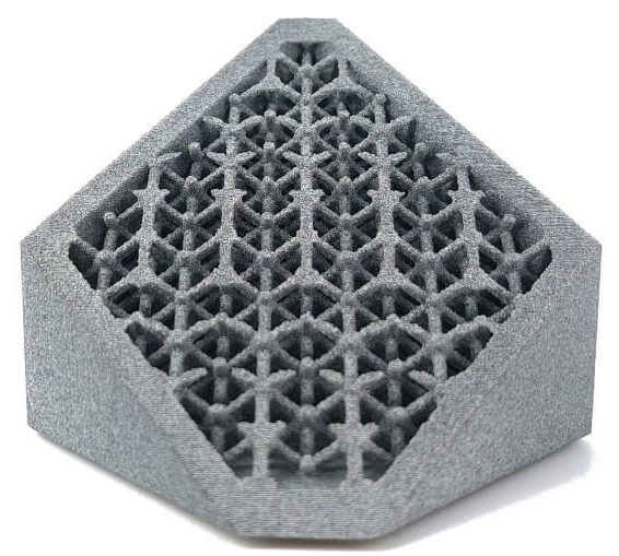
In solid geometries with thick walls, locally high temperatures can develop during the MJF process. These can lead to visible surface defects, uncontrolled shrinkage, dimensional deviations and warpage occur.
To reduce these risks, we replace solid sections with a defined outer shell and a three-dimensional lattice structure inside the part.
- Outer shell: Closed structure that defines the part geometry, surface and dimensional accuracy.
- Lattice: Three-dimensional lattice structure that stabilizes the outer shell and improves thermal behavior during the printing process.
- Powder core: The powder remains inside and is lightly sintered. The part therefore does not contain an empty cavity.
Material-specific configuration
- PA 12 | Classic: Typical shell thickness approx. 3 mm. A solid build can be selected on request.
- PA 12 | Performance: A solid build can also be selected.
- Other PA 12 variants: Typical shell thickness approx. 2 mm. For suitable solid geometries, a lattice structure is required.
- PA 11: For suitable solid geometries, the part is also produced with a shell and lattice structure.
- TPU: Not produced with a lattice structure.
A solid build is particularly useful when extensive mechanical post-processing such as drilling or milling is planned and sufficient solid material is required.
Note: If a solid build is selected against our recommendation, we cannot guarantee our usual quality standards with regard to resulting surface, dimensional or warpage effects.
More complex requirements?
Painting and other special requirements are reviewed individually. In these cases, we recommend an individual quote request.
FDM – Fused Deposition Modeling
For fast, cost-effective prototypes and functional parts with simple to moderately complex geometries.
FDM is the economical choice when short lead times, material variety and a low-cost entry point are the main priorities. Visible layer lines and support contact marks are inherent to the process. For particularly high surface quality, higher functional requirements or complex geometries requiring extensive support, we recommend MJF.
Which material is right for your part?
The choice depends primarily on the application, mechanical loads, temperature and environmental conditions.
PLA
For fast and economical prototypes, presentation models and parts with moderate technical requirements.
PETG
Robust all-round material for functional prototypes and parts requiring greater toughness and resistance.
ABS
For robust technical functional parts with higher requirements for mechanical strength and temperature resistance.
ASA
For technical parts and outdoor applications where weather and UV resistance are important.
Online-configurable options
Part structure
Infill / fill density
- 20 %: lightweight and economical for structural parts
- 50 %: balanced structure for functional applications
- 100 %: fully filled for solid parts
Print parameters
Layer height
- 0.20 mm
- 0.24 mm
- 0.30 mm
Color & production time
- Material-dependent selection of standard colors
- Production times
- Standard: from 4 business days
- Priority: from 1 business day
- Quantity and shipping date calculated instantly
Important technical options
Infill / fill density
Fill density determines how much of the part interior is filled. 20% is suitable for lightweight and economical parts, 50% provides a balanced compromise for many functional applications, and 100% creates a fully filled structure but increases material usage, weight and production time.
Layer height
Layer height affects detail resolution, surface appearance and production time. 0.20 mm is suitable for finer details, 0.24 mm is a balanced standard, and 0.30 mm provides more economical production with a correspondingly more visible layer structure.
When we recommend MJF instead of FDM
FDM is particularly suitable for simple to moderately complex geometries, fast prototypes and applications where a visible layer structure is acceptable. For complex parts with many overhangs or extensive support requirements, as well as for higher demands on surface quality and mechanical properties, we recommend MJF. The process does not require conventional support structures, enabling complex geometries without support contact marks. It also produces significantly more uniform surfaces and largely isotropic part properties. High-performance materials such as PA 12 and PA 11 also provide high load capacity in all directions and good chemical resistance.
LPBF – Metal 3D Printing
For highly loaded metal parts with complex geometries and demanding functional requirements.
The LPBF instant quote includes Stainless Steel 1.4404 (316L) and Aluminium AlSi10Mg. For other metal materials and projects with complex downstream processes, we provide an individual quotation.
Which material is right for your part?
Material selection is based primarily on mechanical loads, weight, corrosion requirements and operating conditions.
Stainless Steel 1.4404 (316L)
Corrosion-resistant stainless steel for functional parts with good mechanical properties and high resistance to a wide range of environmental conditions.
Aluminium AlSi10Mg
Lightweight metal with a good strength-to-weight ratio, suitable for weight-optimized functional parts and technical applications.
Online-configurable options
Manufacturing & surface finish
- Support removal (included)
- Glass bead blasting (included)
- Electropolishing as an optional surface finishing process
Quality & documentation
Order & shipping
- Quantity calculated instantly
- Expected shipping date displayed directly (all materials from 10 business days)
- Neutral packaging available
More complex requirements?
CNC machining and other complex downstream processes are reviewed individually. Materials such as tool steel 1.2709 or Inconel are also not included in the instant quote. For such projects, please use the individual quote request.
