Polyamide 12 · HP 3D HR PA 12 W · Multi Jet Fusion

PA 12 W | Light Gray

Light-colored polyamide 12 for functional parts, visible components, and industrial series production. PA 12 W | Light Gray combines a grayish white to very light gray surface with good mechanical performance and high weathering resistance under the conditions evaluated in the HP test.

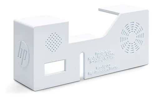
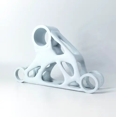
white housing 3D printed from PA 12
Build volume 380 × 284 × 380 mm
Layer thickness 90 µm
Lead time 7 business days
General tolerance ± 0.3% (min. ± 0.3 mm)
Standard finish Depowdered and bead blasted / grayish white to very light gray
Process Multi Jet Fusion (MJF)

Material profile

PA 12 W | Light Gray is an engineering plastic for housings, covers, brackets, and other functional components. The material is processed on an HP Jet Fusion 5620 Pro and is suitable for complex parts, from functional prototypes to series production.
The light-colored surface results from the interaction between the white PA 12 W powder and the agents used in the process. The black fusing agent produces a dark part core, while the exterior appears grayish white to very light gray. The base color is therefore a characteristic result of the process rather than a defined RAL color.

Mechanical behavior
Good combination of strength, stiffness, and ductility
Color
Grayish white to very light gray surface with a dark part core
Weathering resistance
Very good resistance under the UV, temperature, and humidity conditions evaluated
Surface
Matte standard surface with a fine texture
Color options
Can be dyed in a wide range of colors
Geometric capabilities
Complex shapes, integrated features, and accessible internal channels without separate support structures
Technical properties

Key technical properties for evaluating the material.

Tensile strength XY / Z
49 / 45 MPa
Tensile modulus XY / Z
1,900 / 1,850 MPa
Elongation at break XY / Z
17 / 9 %
Elongation at yield XY / Z
11 / 8 %
Notched Izod impact strength XY / Z
4.5 / 4.4 kJ/m²
Density
approx. 1.02 g/cm³

Typical applications

Housings and visible equipment components

Typical parts

Housings, covers, panels, sensor mounts, and custom equipment components.

Why this material?

The light base color is suitable for visible technical components. Fasteners, ribs, and mounting features can be integrated directly into the geometry.

Components for outdoor applications

Typical parts

Sensor housings, covers, brackets, and other components exposed to UV radiation and weathering.

Why this material?

PA 12 W processed on the HP 5600 series showed very good property retention during accelerated weathering. This makes Light Gray an attractive option for applications exposed to UV radiation and moisture.

Colored visible components and controls

Typical parts

Handles, controls, colored covers, and components for visual identification.

Why this material?

The light base color provides a starting point for additional coloring. Function and color can be combined in a custom-manufactured part.

Is PA 12 W | Light Gray the right material?

Light Gray is particularly attractive when a light-colored surface or good weathering resistance is required. If cost, mechanical performance, or surface quality is the sole priority, other PA 12 variants may be a better fit.

Benefits

Light base color

The part needs a light-colored appearance without an opaque coating.

Weathering resistance

UV radiation and moisture are relevant operating conditions.

Color options

The part needs to be dyed or given a specified color finish.

Function and appearance

Mechanical function needs to be combined with a light-colored appearance.

When alternatives make sense

General-purpose functional parts
Alternative: PA 12 | Classic
An established standard option when a light base color is not required.
Cost efficiency
Alternative: PA 12 | Essential
For suitable geometries where cost and functional requirements are the main priorities.
Higher mechanical requirements
A process variant focused on mechanical performance and dimensional stability.
Surface quality and feel
Alternative: PA 12 | Smooth
An alternative for visible components and controls that require a fine surface finish.
Elastic function
Alternative: TPU
For parts that need to undergo substantial, repeated elastic deformation.

Manufacturing and process options

PA 12 W | Light Gray is currently manufactured exclusively using the material-specific “Standard” printing process. Production takes place on the latest MJF system generation used at 3Faktur, the HP Jet Fusion 5620 Pro. Unlike the older HP Jet Fusion 5420, which was developed specifically for PA 12 W, the 5620 Pro uses a black fusing agent. This produces a dark part core with a grayish white to very light gray surface. On the 5420, the core is more bluish and the surface is a cool white with a slight blue tint.

Design guidelines for PA 12 W | Light Gray

The key design guidelines for PA 12 W | Light Gray are listed below. These values are guidelines and may vary depending on part geometry.

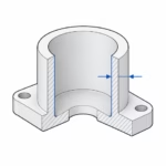
Wall thickness

1.0 mm and above

Larger unsupported surfaces and load-bearing areas require thicker walls or suitable ribbing.

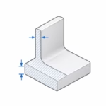
Thick sections

6 mm and above

Thick sections should be hollowed out or given a lattice structure to reduce dimensional deviations, surface defects, and warping. Unless you object, we will make these modifications free of charge. Also avoid abrupt changes in wall thickness.

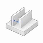
Gaps and clearances

0.5 mm and above

Features positioned too close together may fuse during printing. Please upload separate objects (“shells”) as individual files unless they are physically connected.

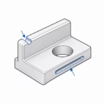
Fine details

0.5 mm and above

Make small details and lettering sufficiently pronounced. Their ability to print successfully also depends on orientation.

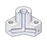
Holes and channels

Ø 1 mm and above, depending on geometry

Powder can be removed from short holes and readily accessible channels. Increase the diameter as the length increases. Long, narrow, or highly curved channels may prevent complete powder removal and should be reviewed in advance.

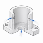
Powder removal from cavities

Openings of Ø 10 mm and above

Hollow parts can be printed, but openings at least 10 mm in diameter must be included so that excess material can be removed. Plan for multiple openings in larger cavities. The powder is compacted during printing, making excess material very difficult to remove.

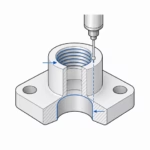
Threads

M6 and above

Threads of sufficient size can be printed if they are included in the CAD data. Please account for the general tolerances. Smaller threads can be tapped after printing. Threaded inserts can be used for connections subject to higher loads or frequent assembly.

The values listed are design guidelines. Very thin structures, large flat geometries, and difficult-to-access internal cavities should be reviewed before manufacturing.

Tolerances, surfaces, and functional features

01

Dimensional accuracy & tolerances

Standard tolerance
± 0.3% (min. ± 0.3 mm)

Influencing factors

Part size
Long dimensions and large flat areas may be more strongly affected by shrinkage and warping.
Part orientation
Orientation affects the dimensional accuracy of individual features and the surface texture.
Geometry and wall thickness
Slender sections, uneven cross-sections, and material concentrations affect cooling behavior and can cause shrinkage or warping.
Post-processing
Blasting, smoothing, coating, and machining can alter dimensions and edges.

Tighter tolerances

In Multi Jet Fusion, loose plastic powder is fused layer by layer. The material shrinks as it cools. The effect of this shrinkage on individual dimensions depends in part on the part geometry and its position in the build.

We control the manufacturing conditions that can be managed, from machines and peripheral equipment to temperature, humidity, and material quality. Even so, not all dimensional deviations can be fully compensated for. Our general tolerance specifies the dimensional variation we offer under these production conditions.

Tighter tolerances are technically possible through targeted optimization of the entire build job. However, the required development and inspection effort generally becomes economical only for very high-volume series production.

Alternatively, individual functional areas can be machined after printing. This additional operation is relatively labor-intensive and costly. It is therefore particularly suitable for complex, high-value parts where precise functional surfaces justify the extra effort.

02

Surfaces

Standard finish
Depowdered and bead blasted / matte surface with a fine texture
The surface texture is shaped by the powder-based feedstock. Surface roughness Ra is typically around 10 µm but varies with orientation: downward-facing surfaces (downskin) generally have the finest texture, while upward-facing surfaces (upskin) are the roughest. Side surfaces fall between the two.

Parts can be oriented at an angle in the build to achieve a more uniform overall surface. Where visible surfaces are clearly defined, the preferred orientation places them facing downward. Please discuss any specific requirements for visible surfaces and surface finish with us before manufacturing.

Upskin

Upskin surfaces are generally rougher in MJF. Larger surfaces, particularly in combination with thick walls, may develop raised edges and depressions toward the center (“sink effect”). Surface roughness is typically Ra 10–15 µm.

Downskin

Downward-facing surfaces generally provide the best surface finish in MJF, with a more uniform texture and lower roughness. Surface roughness is typically Ra 5–8 µm.

Side surfaces

In MJF, stair-stepping generally occurs only on surfaces inclined at a very shallow angle to the build platform. Roughness falls between upskin and downskin and is typically Ra 8–12 µm.

Overall surface improvement

Shot peening or vapor smoothing can be used, for example, to achieve a more uniform feel or reduce surface texture. Available options are listed under “Color, surfaces, and post-processing.”

View post-processing options

Local functional surfaces

Individual holes or mating surfaces can be post-processed selectively. Please note that material removal may expose the dark core.

View post-processing options

Specify in the drawing

Mark visible surfaces, areas to be machined, and any surfaces that need to be masked.

03

Functional features

Threads

Threads M6 and larger can be printed directly if they are included in the CAD data. The general tolerances must be taken into account. Smaller threads can be tapped after printing. Threaded inserts can be used for connections subject to higher loads or frequent assembly.

Fits and bearing seats

Please specify the type of fit and required tolerance in the technical drawing. Tight requirements may require subsequent machining. The necessary machining allowance must be included in the CAD model and agreed with us before manufacturing.

Specify in the drawing

Clearly define the required final geometry, tolerances, fasteners, and planned machining.

Color, surfaces, and post-processing

Light Gray can be used in its light base color or further finished. The appropriate finish depends on color, feel, cleanability, and functional requirements.

Standard finish

Depowdered and bead blasted / very light gray

The surface appears grayish white to very light gray and has a matte, fine texture. The part core is dark. The untreated base color does not correspond to a defined RAL color.

Post-processing

Color

Dyeing

Effect

Changes the surface color without an opaque paint layer

Suitable for

Colored visible parts, identification, and controls

Note

Agree on color requirements using a sample

Surface

Shot Peening

Effect

Produces a more uniform surface and feel

Suitable for

Visible components and controls

Note

The effect depends on geometry and accessibility

Surface

Vapor smoothing

Effect

Reduces the characteristic powder-based surface texture and seals pores

Suitable for

Visible parts, components that need to be easier to clean, and preparation for coatings

Note

Dimensions and color appearance may be affected

Material system

The following information describes the material system used and the basis for assessing its weathering resistance.

Designations & standards

Material
Polyamide 12 / PA 12
Trade name
HP 3D High Reusability PA 12 W
Production system
HP Jet Fusion 5620 Pro
Base color
Grayish white to very light gray
Part core
Black

Quality and documentation

Inspection and documentation are tailored to the requirements of the part. For Light Gray, color, visible surfaces, and the agreed finish are often relevant alongside function-critical dimensions.

Quality assurance

Visual inspection

Inspection for externally visible manufacturing defects, damage, and surface irregularities.

Dimensional inspection

Inspection of agreed dimensions and functional features against the technical drawing.

Appearance approval

Comparison of color and surface finish against an agreed reference sample.

Additional testing

Additional tests can be arranged following a technical review.

Documentation & certificates

Part Manufacturing Record (including test report 2.2)

The digital manufacturing record documents key production information: process decisions, material condition, post-processing, inspection and approval steps, and relevant information for repeat production.

First Article Inspection Report

The First Article Inspection Report documents the inspection of agreed characteristics on initial parts manufactured under the intended series production conditions. It provides the basis for customer approval of series production. The inspection scope and number of samples are agreed in advance.

Inspection certificate 3.1

The inspection certificate 3.1 confirms compliance with the agreed requirements and includes the results of specific inspections assigned to the delivery or defined inspection unit. The characteristics to be inspected and the inspection scope are agreed before the order is placed.

Please specify the required inspection characteristics and documentation when requesting a quote. The quote will define which inspections and documents are included.

Frequently asked questions about PA 12 W | Light Gray

Answers about color, weathering resistance, function, and processing.

What color is PA 12 W | Light Gray?

The untreated surface appears grayish white to very light gray. The color results from the material and the printing process. It does not correspond to a specified RAL color.

Is the part light-colored throughout?

The black fusing agent makes the part core black. Subsequent material removal or deeper damage may expose this core.

Is the material suitable for outdoor applications?

In the HP study, PA 12 W processed on the 5600 series showed very good resistance to accelerated weathering. Loads, temperature, and the required service life must also be considered for the specific application.

Can Light Gray be dyed?

Yes. The achievable color depends on the base color, surface, and finish. If a specific color is required, a sample with the intended finish should be approved.

How can I achieve a precisely specified color?

Specified color requirements can be met through an agreed dyeing or painting process. Please specify the required color and, if possible, provide a physical reference sample.

Can I sand or mill Light Gray?

Machining is possible. However, it may remove the light-colored outer surface and expose the dark core. For visible areas, the subsequent color and surface finish should be taken into account.

Are printed parts automatically leak-tight?

Leak-tightness depends in part on geometry, wall thickness, process, medium, and pressure.

What information do you need for series production?

In addition to the 3D data, we need the quantity, critical dimensions, operating conditions, and required finish. A reference sample is useful if specific appearance requirements apply.

Request a quote for PA 12 W | Light Gray parts

Request a quote for your 3D data. For series production projects or special requirements, please also provide a drawing with critical dimensions and information on color, surface finish, and operating conditions.

Request a quotation
scroll on top