The Part Manufacturing Record is an optional certificate available for parts manufactured by 3Faktur. It serves as a Certificate of Compliance, but provides significantly more detailed technical information.
The certificate documents key manufacturing information: process decisions, material condition, post-processing, inspection and release steps, as well as relevant information for repeat production.
It makes transparent the technical conditions under which a part was produced — and which factors influence quality, traceability and reproducibility.
Certificate contents
What the Part Manufacturing Record makes transparent
Orientation, print mode, cooling strategy and build-volume utilization.
Material system, refresh rate and oxidation monitoring.
Dyeing, smoothing, blasting or other documented post-processing.
Visual inspection, weight check, final release and traceability.
Through documented orientation, parameters, material handling and post-processing.
1 Part orientation
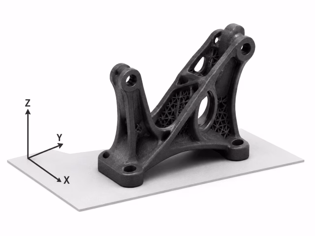
The part orientation describes how a part is positioned within the build volume. This decision affects surface quality, dimensional accuracy, thermal warpage, mechanical behavior and repeatability.
In Multi Jet Fusion, orientation is a key process decision. It determines which surfaces face upward, downward or sideways in the build volume, the direction in which layers are built, and how heat is distributed during the process.
1.1 Influence of part orientation on surface quality and dimensional accuracy
Click the areas you are interested in.
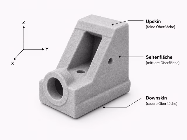
Orientation determines which surfaces are created as upskin, downskin or side surfaces. In the MJF process, these surfaces differ significantly in surface quality.
Downskin surfaces typically show the most favorable surface characteristics because they are supported by the powder bed. Upskin surfaces are usually more critical: the application of process fluids and thermal effects can locally increase roughness, create edge build-up or lead to burr formation. Side surfaces are generally between these two extremes.
In addition, the angle relative to the layer plane affects the surface appearance. Visible stair-stepping effects can occur on curves or shallow angles. An angled orientation can make surface characteristics more homogeneous across several faces, but may also reduce dimensional accuracy or build-volume utilization.
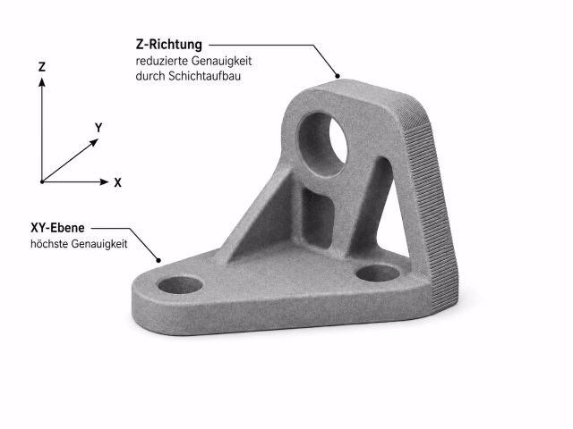
Orientation affects the direction in which critical dimensions are built. Dimensions in the XY plane are typically easier to control in MJF because contours are defined directly within the layer plane. Dimensions in the Z direction, on the other hand, are created across many individual layers and depend more strongly on layer build-up, thermal shrinkage and process control.
Important: dimensional deviations often act relative to part length. For long parts, an upright orientation can therefore lead to significantly larger absolute deviations than a flat orientation. Building a long geometry in the Z direction can accordingly have a strong negative effect on dimensional accuracy.
At the same time, an upright or angled orientation can offer other advantages, such as better curves, more homogeneous surfaces or less visible stair-stepping. Orientation is therefore always a trade-off: dimension-critical lengths, functional surfaces and fit areas must be evaluated against surface quality, curves, build-volume utilization and process stability.
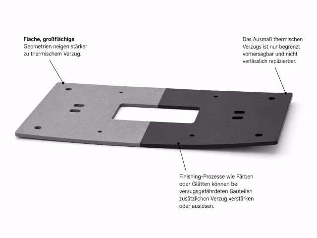
Thermal warpage is caused by uneven heating and cooling within the part and the surrounding powder. Large, flat geometries are particularly critical because stresses can build up across their length or surface area. Warpage can be reduced through process strategy, orientation and placement, but it can never be completely eliminated.
Orientation plays a central role here. Parts at risk of warpage are preferably oriented flat in the XY plane, ideally with the longest dimension along X/Y. This reduces part height and places the geometry more favorably within the thermal process window.
In addition, there are areas within the build volume with a lower tendency toward warpage. Critical parts are preferably placed in these areas. This can limit the available build-volume capacity because not every free position in the build volume is equally suitable. A warpage-optimized manufacturing strategy can therefore increase cost and lead time.
Geometric details can amplify this effect. Domes, upright walls, solid areas or other elements that retain heat for longer cool differently than thin or flat areas. This uneven cooling creates internal stresses and can ultimately lead to warpage.
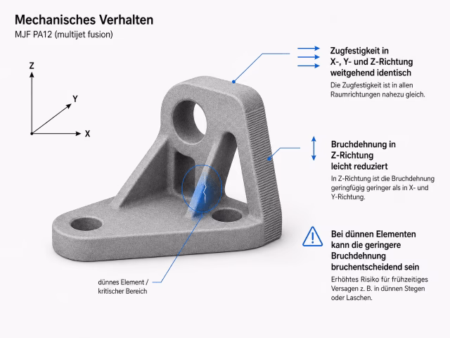
MJF parts made from PA12 generally show largely isotropic mechanical behavior. Tensile strength is typically very similar in the X, Y and Z directions. Orientation is therefore less critical in MJF than in more strongly anisotropic additive manufacturing processes.
However, elongation at break remains relevant. It can be reduced in the Z direction because the part is built layer by layer and loads may act more strongly across the layer structure. For many parts, this is not critical. For thin, flexible or highly loaded elements, however, reduced elongation at break can be decisive and increase the risk of cracking or fracture.
Highly loaded or deformation-relevant areas should therefore preferably be oriented so that critical loads act mainly in the XY plane. Orientation is evaluated not only according to strength, but also according to deformability and fracture behavior.
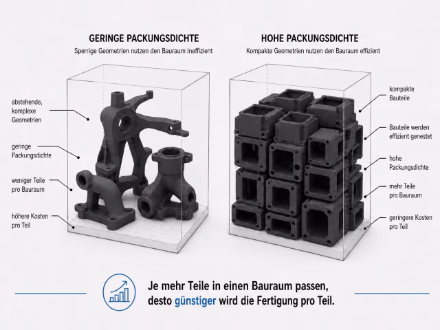
A space-saving orientation increases packing density within the build volume and can reduce manufacturing costs. However, this economic optimization is not always identical to the best technical orientation, because visible surfaces, functional surfaces or warpage risks may need to be prioritized differently.
For series parts, it is not only a good individual orientation that matters, but consistent repetition across multiple production runs. If orientation and placement logic remain stable, surface appearance, dimensional behavior and process conditions can be reproduced more reliably.
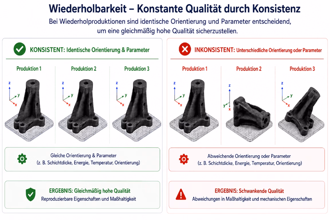
The best orientation depends on the part geometry and the desired properties. An angled orientation can improve surface quality, but may reduce dimensional accuracy, build-volume utilization or reproducibility. A space-saving orientation can lower costs, but is not automatically the best choice for visible surfaces or dimensional accuracy.
1.2 How 3Faktur defines orientation
PA 12 | Classic / Performance
Quality-optimized orientation with the best possible balance of surface quality, dimensional accuracy and process stability.
PA 12 | Essential
Cost-optimized orientation. Consistent across batches, but more often space-saving within technically reasonable options.
PA 12 | Smooth
Orientation focused on surface homogeneity and downstream surface quality.
1.3 Repeat production
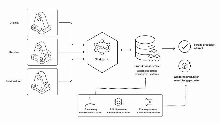
Consistency is crucial for repeat production. Parts that have already been produced by 3Faktur should be manufactured as identically as possible in later orders — including new revisions or individualized variants.
For this purpose, 3Faktur has developed its own software solution that recognizes parts during work preparation. Using internally developed AI methods, geometric similarities between parts are identified. This makes it possible to reliably determine whether a part or a comparable variant has already been produced.
When a match is detected, orientation as well as relevant layer and process parameters are consistently adopted from the production history. This makes repeat production more reproducible, more efficient and less dependent on manual decisions.
2 Process parameters
2.1 Parameter overview
The process parameters describe key process conditions of the production run. They show which machine platform and process strategy were used to manufacture the part.
This information is relevant because additive manufacturing is highly process-dependent. The same geometry and the same material do not automatically lead to the same result if the machine platform, print mode, cooling, build-volume utilization or post-processing differ.
| Parameter | Description | Relevance |
|---|---|---|
| Machine platform | Machine type used. | The machine platform is part of the qualified process window. It influences the material variant, available process strategy and reproducible part quality. |
| Print Mode | Defined parameter set for the printing process. | The print mode documents which process parameters were used to manufacture the part. |
| Cooling strategy | Defined cooling strategy after printing. | Cooling can be faster and cost-optimized or slower and quality-oriented. Slow cooling reduces thermal stresses, but typically extends the process by 1 to 1.5 days. |
| Layer thickness | Layer thickness in the printing process. | Layer thickness affects detail resolution, surface appearance, stair-stepping effects, process time, mechanical load capacity and process stability. |
| Packing density | Utilization of the build volume by the parts produced in the job. | A lower packing density can be more favorable from a process perspective, but is more cost-intensive because fewer parts are produced per job. A higher packing density improves cost efficiency, but depending on geometry and material, it can influence thermal conditions and therefore part properties. |
| Manufacturing History | Comparison with previous production runs. | Documents whether the part has been manufactured before and whether relevant parameters from previous production runs were adopted. Note: this information is currently being prepared technically and has not yet been implemented. |
| Lattice Structure | Lattice structures in solid part areas. | Solid areas can locally cause high process temperatures and thereby negatively affect dimensional accuracy, surface quality and mechanical properties. A suitable lattice structure can reduce these effects while retaining a large proportion of the compressive load capacity of the solid material. |
| Post-processing | Documented post-processing steps. | Lists all optional or additional processing steps, such as dyeing, smoothing, blasting or other surface treatments. This makes it clear which process steps after printing are part of the delivered part quality. |
2.2 Print Mode
Balanced
Balanced process control. The goal is a stable series-production process with good part quality and economical production time.
Layer thickness: 80 µm
Variants:
PA 12 | Classic
PA 12 | White
PA 12 | Smooth
Fast
Productivity-oriented process control, with a stronger focus on speed and cost.
Layer thickness: 110 µm
Variants:
PA 12 | Essential
Robust
Process-reliability-oriented process control for demanding geometries or critical part areas.
Layer thickness: 90 µm
Variants:
PA 12 | Performance
2.3 Machine platform
3Faktur works with several industrial HP Multi Jet Fusion systems. The systems differ in material approvals, process windows, productivity and quality profile.
- HP MJF 5210 Pro: used for PA 12 | Classic and PA 12 | Essential
- HP MJF 5420: used for PA 12 | White
- HP MJF 5620 Pro: used primarily for PA 12 | Performance and PA 12 | Smooth
Material system
The material system describes the controlled material environment. In powder-based processes, not only the material name is relevant, but also the material platform, refresh rate and material condition.
| Parameter | Description |
|---|---|
| Material Type | We offer our materials in different processing variants. You can find the current variants on our overview page PA 12 variants. |
| Material System | Three types of PA 12 are used: HP 3D HR PA 12 from Evonik (variants PA 12 | Classic, Essential and Performance), HP 3D HR PA 12 W from Evonik (variant PA 12 | White), and HP 3D HR PA 12 S from Arkema (variant PA 12 | Smooth). |
| Refresh Rate | Indicates the proportion of fresh powder in the build job. This is typically 15 – 20%. |
| Oxidation Monitoring | The oxidation state of the powder is determined using the b* indicator. A value that is too high indicates reduced powder viscosity, which can lead to increased pore formation and up to 90% lower mechanical load capacity. |
Inspection and release steps
The inspection and release steps document selected controls and the release process. This shows whether the batch has been inspected, released and is traceable.
| Control | Description | Relevance |
|---|---|---|
| Visual inspection | Inspection of visible deviations, such as incomplete areas, damage or noticeable surface defects. | Quick control point for externally visible process or handling deviations. |
| Weight check | Comparison of the part weight with the expected range. | Weight deviations can indicate process errors. |
| Final inspection | Confirmation that defined process, inspection and release steps have been completed. | Formal completion of the quality-relevant process chain. |
| Batch Traceability | Traceability of the batch. | All essential production parameters are documented and traceable. |
Why 3Faktur can issue this certificate
The Part Manufacturing Record is only possible because 3Faktur understands additive manufacturing as an end-to-end digital production process. Work preparation, manufacturing, material handling, post-processing and quality assurance are digitally connected. This enables relevant process data from different production steps to be captured in a structured way and made available for technical documentation.
This is digital manufacturing in practice: standardized processes, a high degree of automation, digital traceability and reproducible manufacturing decisions. The record is therefore not retrospective reporting, but an extract from a controlled, digitalized and quality-oriented manufacturing environment.
