
Additive manufacturing, also called 3D printing, has advanced from a prototyping to a manufacturing technology. Of course, this only applies today to a tiny part of the industrial manufacturing, however, the share of additive technologies in global manufacturing is growing fast. Only between 2011 and 2015, the market for additive manufacturing was growing with an annual growth rate of (CAGR) of ~32%.
But how do 3D printed parts compare to other manufacturing methods? The answer is, as always, it depends. Factors are, amongst others, the additive technology (e.g., powderbed vs. liquid resin technology), the machines, materials, geometries, etc. used.
In this article, we give a short overview about the key characteristics of 3D printed parts. This will help you to evaluate, whether additive manufacturing is a manufacturing option for your parts.
Surface Properties
The surface properties in 3D printing are dependent on the technology, material and orientation in the printer. In general, liquid-based systems like Stereolithography achieve the best surface properties (roughly Ra 1 -5 µm), however, without finishing, the surface is not homogeneous (support structure scars). Powder-based systems, such as laser sintering and multi jet fusion, have a rougher surface (Ra 10 – 15 µm), however, the surface is more homogeneous, since no support structures are required.
Example: magnified surface of Stereolithography parts (bottom side after support removal) – with and without finishing.
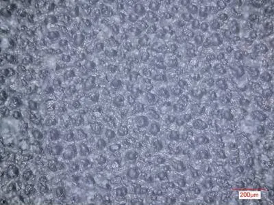
SOURCE: 3Faktur & EAH Jena.
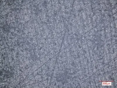
SOURCE: 3Faktur & EAH Jena.
Stereolithography
How the technology works: a liquid, UV-sensitive, resin (mostly epoxy resins) is selective cured by a UV-laser.
Surface quality: Ra values of 1 µm or even less are with post-processing. Raw parts have Ra values between ~1 µm – 13 µm depending on the side (e.g. top smooth, bottom rough).
Impact on surface properties:
- Liquid material: surface properties are excellent compared to extrusion or powderbed technologies (no grains or gaps on the surface)
- Orientation:
- The horizontal, top side (X-Y) of the part is excellent (Ra values in the magnitude of 1 µm – 5 µm, depending on machine and material)
- The vertical side (Z), may have some small layer steps. Rough Ra value: [µm] ~2 – 7.
- The horizontal, bottom side (X-Y) is the worst surface in SLA 3D printing. Stereolithography requires support structures, their contact points cause the surface to be rather rough. Untreated Ra values are > 10 µm, with surface finishing, the surface can be improved significantly
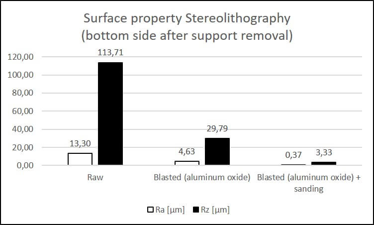
Surface roughness Ra & Rz [µm] of Stereolithography 3D printed parts. The measurements were taken on the bottom side, so they refelect the worst properties in Stereolithography printed parts. SOURCE: 3Faktur & EAH Jena.
Multi Jet Fusion
How the technology works: plastic powder (mostly Nylon 12) is selectively coated with a heat-conductive liquid. When exposing the areas with a heat source, the areas coated with the fusing agent melt, while the powder around remains loose. More information on HP Multi Jet Fusion.
Surface quality: finished parts (blasted) with Ra values of ~5 µm. Raw parts show Ra values around 10.
Impact on surface properties:
- Powder-based technology: the surface consists of partially melted powder grains (raw material grain size ~60 µm), therefore the surface is comparably rough.
- Orientation:
- Since no supports structures are required, the surface roughness is rather homogeneous.
- There can be stepping lines along the Z axis (horizontal), but those are normally not significant (~ 80 µm layer height)
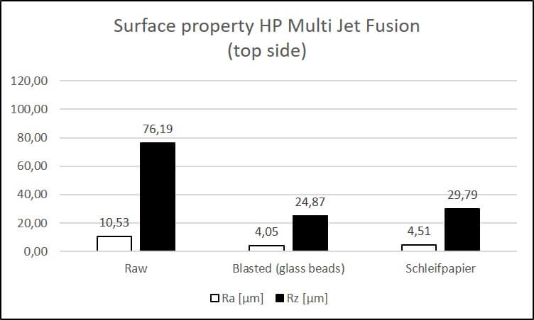
Surface roughness Ra & Rz [µm] of Multi Jet Fusion printed PA12 parts. The measurements were taken on the top side (X-Y). SOURCE: 3Faktur & EAH Jena.
Other technologies
Two other common technologies are Fused deposition modeling (FDM) and Polyjet printing. Whereas FDM 3D prints have low surface qualities, Polyjet prints can be polyished to Ra values of < 1 µm. Those two technologies and more details and data you can find in this article: The surface properties of different 3D printing technologies.
Additional aspects
Surface patterns: surface patterns, cannot be realized, unless the patterns are strong (> 0.3 mm). The best technology to realize surface patterns is Stereolithography.
Scratch / Abrasion resistance: The resistance to scratches and abrasion is strongly material-dependent. While Multi Jet Fusion 3D printed PA12 (Nylon 12) is very abrasion resistant, photopolymers are not (Stereolithography and Polyjet). Scratches can be slightly seen in PA12 (powder grains on surface), transparent photopolymers are less prone to scratches.
Coating: All of our materials can be coated. It is recommended to use plastics primers, however, for prototypes without any mechanical stress, spray paint can be applied even without primer.
Our finishing methods:
- Sanding: Stereolithography, Polyjet (Ra of ~1 or less µm possible)
- Bead blasting: PA12; mainly for cleaning purposes (standard finishing for all PA12 parts)
- Shot Peening (ceramics): PA12, surface roughness not significantly changed, however, parts become more shiny and homogeneous.
- Coating: all materials
- Dyeing (Black): PA12 (HP Multi Jet Fusion)
More Information
The surface properties of different 3D printing technologies
Tolerances & Reproducibility
To understand tolerances and reproducibility in additive manufacturing, it is important to know the potential error sources:
- Meshing (converting STP to STL): a STL file is not identical with a STP file. Converting STPs to STLs (necessary in 3D printing) causes errors, which influence the accuracy of the printed part. In particular low resolutions leads to poor surface quality and inaccuracy in curves and angles. Do not underestimate the magnitude of this factor, in case of doubt, send us the STP files, we will export hem in an optimal resolution.
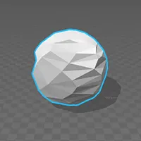
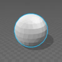
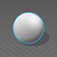
STL (Mesh) file of a sphere, in 3 different resolutions (surface deviation of 0.5, 0.1, 0.01 mm, left to right). The low resolution (‘low poly’) files would not create a useable physical model. For high resolution 3D printing technologies, like Multi Jet Fusion, Stereolithography and Polyjet, we recommend a surface deviation of 0.05 mm or better. Source: 3Faktur
- Machine inaccuracies: Machine inaccuracies differ by part, batch and position within the build space. Besides mechanic inaccuracies, material properties play a big role. In thermal processes (e.g. multi jet fusion or laser sintering), warpage can occur. For photopolymers, shrinkage can be one source of error. Typical tolerances by technology are:
- Multi Jet Fusion: ± 0.2 %, with a lower limit of 0.2 mm
- Laser sintering: ± 0.3 %, with a lower limit of 0.3 mm
- Stereolithography: ± 0.2 %, with a lower limit of 0.2 mm
- Polyjet: ± 0.15 %, with a lower limit of 0.15 mm
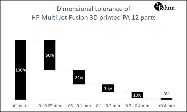
3D printed parts (HP Jet Fusion, material PA12) deviation to intended size. Sample size = 100 from random batches. All dimensions (x,y,z) were measured. Source: 3Faktur
- Orientation within the machine: for each part and machine, we chose a certain orientation of the part. This causes some errors, since the resolution in the X-Y axis is for almost all 3D printing technologies higher than in the Z-axis.
Let’s take a circle, printed on the X-Y axis, the shape of the printed circle will be (almost) perfect, since there are no ‘steps’ in the shape. However, printed along the Z-axis, the circle will be made of ~0.1 mm steps (layer height dependend on technology), caused by the layer thickened of the machine. This is a main factor in the reproducibility of parts, they should be always printed in the same orientation and on the same machine.
What does that mean for you? If you reorder a part that you have ordered less than 3 months ago, we will print it in the same orientation. Feel free to remind us that the part was printed before, in particular, if the name has changed. If you need us to save the part orientation for more than 3 months, please send us a note. - Post process finishing: In SLA and Polyjet, support structures are applied an partly removed by sanding, which can affect the minus tolerance. PA12 parts are blasted, which might affect edges and angles.
More information
Mechanical Properties
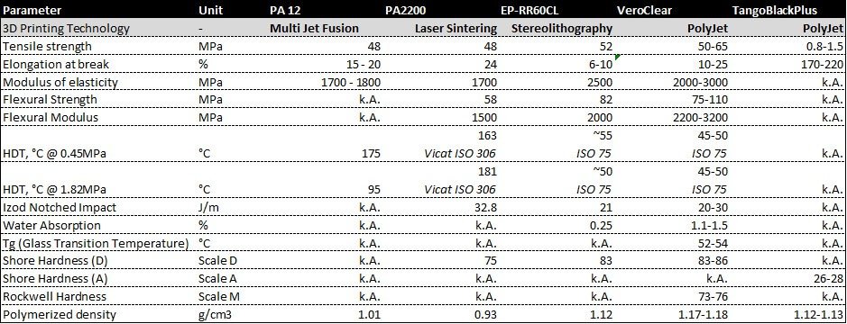
Mechanical properties by material and technology. Source: material data sheets and 3Faktur.
The mechanical properties depend on both, material and technology. A short overview:
PA12:
- Multi Jet Fusion PA12
- Parts are dense, with few pores (part density equals roughly the raw material density of 1.01 g/cm³)
- The parts are widely fluid tight. See also: the fluid tightness of Multi Jet Fusion PA 12 parts for more information (recommended shape and wall thickness of vessels).
- Anisotropy is minimal, parts are widely isotropic.
- Material properties equal widely injection molded parts
- Can be used for end-use parts
- Laser sintered PA12 parts:
- The parts are porous (density ~0.9 – 0.98 g/cm³; raw material density 1.01 g/cm³).
- The parts are light and not water tight
- Laser sintered parts show some anisotropy, i.e., the mechanical strength along the Z axis is lower than on the X-Y axis
Resins
- Stereolithography:
- Epoxy resins with little anisotropy
- Materials have low resistance to UV light and therefore age fast
- Rigid material, low flexibility
- Not recommended for end-use parts
- Low abrasion resistance
- Polyjet
- Acrylic resins with wide range of properties (soft to rigid)
- Materials not recommended to use for end-use parts (fast aging)
- Low abrasion resistance
Speed Production
The production speed is an often-discussed topic. In the media and even from some service bureaus, you often read ‘over-night service’. Prints in one day can be possible, however, there are some limitations:
- Reliability: 3D printing is used for low quantities of up to a few thousand parts. Therefore, the reliability is not comparable to large-scale production machines. A failed print happens across all technologies and occurs in up to 10% of times.
There can be several reasons for those failures. They can be a result from warping of the part within the print process (e.g. laser sintering), broken print heads (e.g. Multi Jet Fusion), machine or software failures.
Therefore, a part production within 24h cannot be guaranteed. In case of a print failure, the time is mostly not sufficient to reprint the part and complete the finishing (see next chapter). - Finishing: All parts go through a rigorous finishing process, which in most cases takes up to a day before all steps are finished. Just printing the part would not ensure the quality you expect from us. Standard finishing differs by technology, e.g.,
- Multi Jet Fusion:
- Cleaning the parts from excess powder
- Bead blasting to remove the remaining powder residues
- Cleaning parts with air pressure to remove excess beads from blasting
- Stereolithography
- Washing parts in Isopropyl alcohol
- Removing support structures
- Sanding surface
- Post-curing (UV)
- Multi Jet Fusion:
- Printing cycles: The time for one printing cycle depends on the technology (see table for detailed information). In HP Jet Fusion, the printing speed is very fast (about 30 mm per hour), however, cooling a build unit takes roughly 2 days. In Stereolithography, the printing speed is lower (5 – 10 mm per hour), however, there is no cooling required. Hence, the absolute printing time in Stereolithography is shorter.
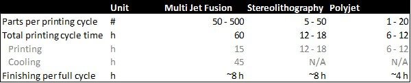
Printing cylce times by technology. HP Multi Jet Fusion requires the most time, but allows the production of a larger number of parts at the same time. Source: 3Faktur
About 3Faktur: 3Faktur specializes in 3D printing, rapid prototyping, and rapid manufacturing. We utilize HP’s Multi Jet Fusion technology and offer various materials for prototyping and series production. If you have any questions about your project, feel free to contact us.
