
Source: 3Faktur, EAH Jena
The surface quality varies significantly among different 3D printing processes. In addition to the printing process itself, the nature of the printed object and its positioning in the printer also play a significant role in determining the surface quality. For processes that require support material, special attention is required for areas where the support material contacts the actual object.
We have provided detailed information on the surface properties for each 3D printing technology.
Liquid Photopolymers (Stereolithography)
Selective Curing of Liquid Polymers
Several 3D printing processes operate based on this principle, including Stereolithography (SLA/STL), Digital Light Processing (DLP), Two-Photon Polymerization (2PP), and Continuous Liquid Interface Production (CLIP). These processes always require support structures.
The liquid starting material is selectively cured at the specified locations. The mentioned processes differ in the light sources used (Stereolithography → laser; Digital Light Processing → projector) and the resolution in the Z-direction (CLIP → no layers; all other processes have layer thicknesses of 20 – 100 µm) and X-Y-direction (2PP: nanometer-level resolution).
Surface Quality
The surface roughness of Stereolithography differs significantly depending on the orientation in the printer. While the top side already achieves a roughness (Ra value) in the low single-digit µm range without post-processing, the underside is very rough due to the support structures.
However, the material (based on epoxy) can be easily post-processed. Since the material is largely free of pores, excellent surface values can be achieved through sandblasting or manual sanding (see figure for details).

Figure: Surface roughness of Stereolithography
Source: 3Faktur; EAH Jena
Finishing Options
The support side is usually processed with sandpaper. To achieve homogeneous surfaces, objects can also be sandblasted (typically using corundum).


Figure: Microscopic images of the surfaces (underside) of Stereolithography components
Source: 3Faktur; EAH Jena; Printed on a Raplas 450 HD printer with RR60Cl material (high-resolution epoxy).
Applications
The objects are largely pore-free, and excellent surfaces can be achieved through repeated sanding. As a result, these objects can be used not only for “normal” rapid prototyping applications but also for creating molds or for applications that require painting.
Layer Structure (Schematic)

- X – Y Plane: Surfaces printed horizontally to the build platform exhibit a very good, smooth surface. An exception is the surfaces where support structures are attached, where residues may be visible (not shown in the illustration).
- Z Plane: The layers are perceptible due to minimal inaccuracies during printing or due to transitions being realized only at the distance of one layer (usually ~50 – 100 µm) and not continuously (illustrated on the right and left). These layers can be largely removed through (abrasive) post-processing (red line).
- Special Feature: Since the printing process usually does not occur in a vacuum, minimal air inclusions may form. However, they are usually not visible to the naked eye.
Print Example
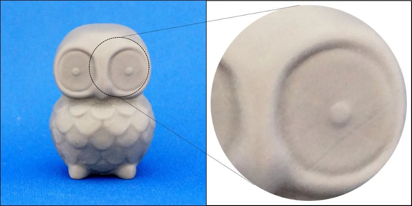

Print Example
This 4.5 cm tall owl figure was printed in gray Stereolithography standard material. Even in the highly magnified view, the printing layers are hardly recognizable. Only sporadic layers can be identified.
Powder-Based Processes (HP Multi Jet Fusion, SLS, Colorjet, SLM)
Powder-Based Processes
The best-known and most commonly used processes are HP Multi Jet Fusion, Selective Laser Sintering (SLS), and the Colorjet process. In these processes, powdered starting materials are selectively bonded. This can be achieved through a chemical process (binding) as in the Colorjet process or through a thermal process (SLS → laser; HP Multi Jet Fusion → infrared). With the exception of metal printing (SLM), support structures are not necessary in these forms of additive manufacturing, as the object is fully embedded in the powder material.
Surface Quality
The surfaces of the objects have good quality. The absence of support structures results in mostly homogeneous surfaces. Due to the nature of the material (∅ approx. 60 µm powder grains), holes/pores may appear on the object’s surface. As a result, completely smooth surfaces cannot be achieved even through sanding. However, the processes differ in this regard; for example, Selective Laser Sintering produces more porous parts than the HP Multi Jet Fusion process (More details: Lasersintern vs. HP Jet Fusion).


Figure: Surface Roughness of Laser Sintering & HP Jet Fusion
Source: 3Faktur; EAH Jena
Finishing Options
Common post-processing methods include grinding, blasting, or vibratory finishing (especially for SLS). These can smooth the surfaces, but the surface quality achieved by liquid-based processes cannot be reached. Generating a nearly pore-free surface requires significant effort (vacuum infusions or a multi-stage process of surface filling with subsequent multiple sanding).
In the example below, laser-sintered parts were infiltrated with epoxy resin in a vacuum and then sanded. By closing the pores, a very good surface quality can be achieved. However, this is generally too labor-intensive for most cases. When Ra values of 1 µm (+/-) are required, stereolithography or the PolyJet process are usually chosen.


Figure: Microscopic images of laser-sintered part surfaces
Source: 3Faktur; EAH Jena; The printing was done on an EOS P390 with PA2200 material.
Applications
All typical applications of Rapid Prototyping and functional parts (Rapid Manufacturing). Especially Multi Jet Fusion and Laser Sintering are popular processes for producing fully functional parts due to their cost efficiency, high part quality, and speed.
Layer Structure (schematic)

- X – Y Plane: Homogeneous surfaces are not possible due to the powdered form of the material, resulting in the formation of tiny pores.
- Z Plane: The same applies here as for the X-Y plane due to the nature of the process.
- Special Feature: Pores can be partially “closed” through infiltration. Sanding only provides limited improvement in quality.
Print Example


Design: Thingiverse | LuluPaw
Laser Sintering Print Example
The surface in Laser Sintering is slightly finer, but the layers of the 4.5 cm tall owl are still clearly visible.
Extruded Plastic (FDM/FFF)
Extruded Plastic
There is a variety of processes that use this technology. The most well-known ones are FDM/FFF (Filament 3D Printing), special extrusion processes such as fiber-reinforced systems (carbon/glass fibers), injection-based systems (bio 3D printers, food printers, cement printers). Support structures may be necessary depending on the model. The processes work according to the following principle: a thermoplastic material is extruded through a nozzle and solidifies as it cools down.
Surface Quality
The quality of the surfaces is generally low to moderately good. The outer layers (in the Z-direction) have visible grooves, but they are nearly pore-free and can be brought to a high-quality level through post-processing. The underside, where there is no support, is usually very smooth, while the top surface roughness is comparable to other 3D printing technologies (see data below).
In areas with support material, the surfaces may be heavily affected. However, some printers use water-soluble support materials, which allows for significantly better quality.

Source: 3Faktur; EAH Jena
Finishing Options
For PLA and PA6/PA66, finishing usually involves the removal of support material. ABS can be post-processed quite well and can be sanded, blasted, or tumbled.

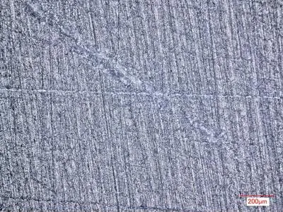
Figure: Microscopic images of FDM part surfaces
Source: 3Faktur; EAH Jena; Printed on an Ultimaker 3 using ABS material (Ultimaker).
Applications
The most common applications for objects made from extruded plastic are functional parts. They are not suitable for making molds or for painting without significant effort.
Layer Structure (schematic)
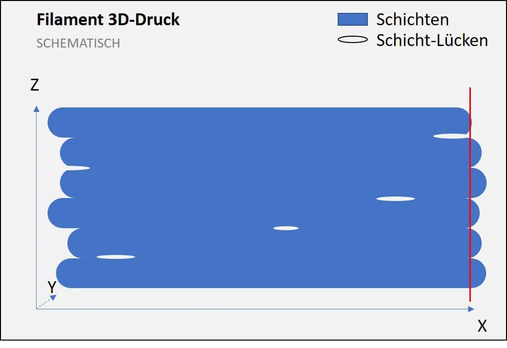
- X – Y Plane: The surface is less grooved, but individual layers are perceptible (due to the printing direction of the nozzle).
- Z Plane: The layers may vary in appearance; smooth surfaces in the Z-direction are possible, especially for ABS (red line).
- Special Feature: Gaps between layers are possible due to the process → reduction of tensile strength in the Z-direction.
Print Example


Design: Thingiverse | LuluPaw
Print Example
FDM prints exhibit visible grooves. They can be post-processed differently depending on the material. The PLA shown here can be post-processed to a limited extent. In contrast, ABS can be mechanically and chemically refined quite well.
Photopolymer-Jetting (Polyjet/Multijet Modeling MJM)
Selective Deposition of Photopolymer Drops
The most well-known processes in this category are Polyjet and Multijet Modeling. In these processes, light-curable polymers are deposited onto a build platform through a print head with multiple nozzles. The still liquid material is immediately cured by UV light. Support structures are always necessary in these processes.
Surface Quality
These processes yield good to very good surface quality. The deposited material droplets spread to very small layer heights, resulting in very homogeneous surfaces with barely noticeable layer thicknesses (15 – 30 µm). Support structures are also necessary and can significantly affect the quality of the affected areas. However, for 3D printers that use thermally soluble (3D Systems) or water-soluble (Stratasys, Keyence) support materials, this limitation no longer applies. Due to the use of material droplets, the deposition layers are visible in the X-Y direction (movement direction of the print heads).

Source: 3Faktur; EAH Jena
Finishing Options
Removing support structures is necessary for “normal” Polyjet printers. With water- or thermally soluble support, post-processing is often not necessary. Techniques such as blasting and sanding are particularly used, which can achieve very good surface values (see figure below).
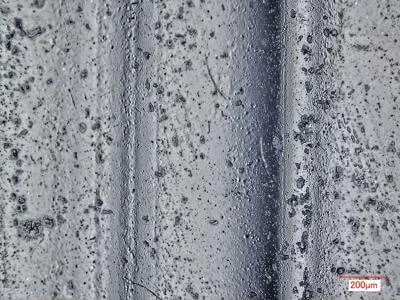

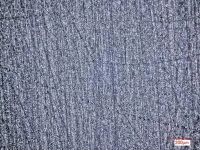
Figure: Microscopic images of Polyjet part surfaces
Source: 3Faktur; EAH Jena; Printed on a Stratasys Objet 350 using VeroBlack material.
Applications
Similar to selective curing, the surfaces are largely pore-free and can be further improved through repeated sanding. Therefore, the objects are suitable not only for typical rapid prototyping applications but also for creating master molds.
Layer Structure (schematic)
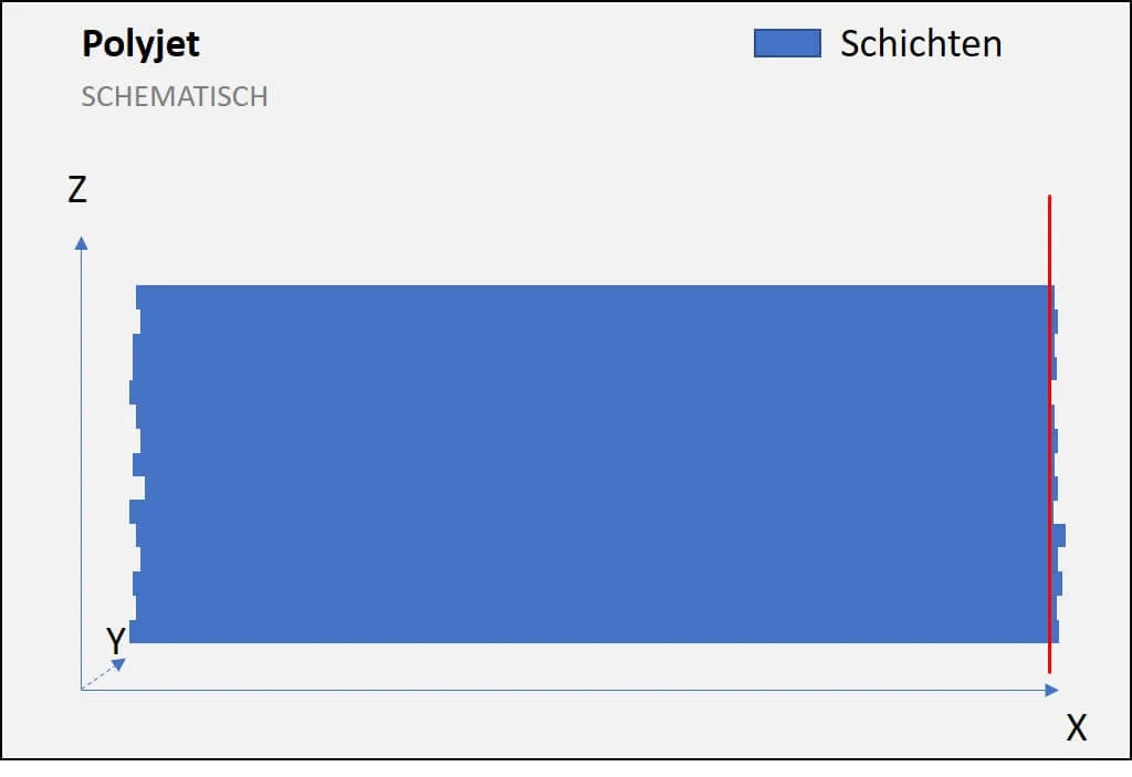
- X – Y Plane: Minimal layers are created due to the movement paths of the print heads.
- Z Plane: Minimally present noticeable layers can be smoothed through subtractive methods (red line).
- Special Feature: Layers are present in all planes (not shown).
About 3Faktur: 3Faktur specializes in 3D printing, rapid prototyping, and rapid manufacturing. We utilize HP’s Multi Jet Fusion technology and offer various materials for prototyping and series production. If you have any questions about your project, feel free to contact us.
