
When we deal with 3D printing, the term “Reverse Engineering” inevitably comes up. Translated somewhat simply, it means “reverse development.” In this article, we want to take a closer look at this term and explain the special role of 3D printing technologies in the process of reverse engineering.
The Concept of Reverse Engineering
In essence, Reverse Engineering (RE) is the process of “recreating” an object by examining its structure, states, and responses to environmental changes, in order to develop a construction plan. It involves reversing the original construction process.
Reverse Engineering is used, for example, for the analysis of heavily stressed components’ wear or for replicating parts for which no construction data (anymore) exists, particularly in the case of older plants or vehicles.
The goal is to represent the existing object as accurately as possible, usually in the form of a 3D model of the original item. This often requires partial or nearly complete disassembly of the object. In some cases, a professional 3D scan is sufficient for certain objects.
The Contribution of 3D Printing Technologies to Reverse Engineering
The technologies that have (further) evolved around 3D printing have significantly advanced the possibilities of reverse engineering. 3D scanning technologies, in particular, simplify the digitalization of objects, reducing the need for disassembly and greatly accelerating the process.
3D printing, on the other hand, allows for the easy and cost-effective production of additional models for comparison with the original or for “copying” the object. The former is often used to analyze heavily stressed parts. For example, manufacturers examine which areas of a mechanical component in an engine experience the most wear. The data obtained from this analysis can be directly used to produce revised parts using additive manufacturing processes. These parts are then either subjected to further testing or, in some cases, directly integrated. 3D printing offers the ability to create highly complex geometries that cannot be realized or are very cumbersome to produce using other manufacturing methods.
The process of “copying” comes into play when parts are needed for which no construction data is available. This is often the case with older plants, especially in the field of special machine construction. Another increasingly popular application is the production of spare parts for vehicles or even airplanes.
Methods Used
For reverse engineering, a particularly accurate measurement of the original object is required. Two approaches have been established: 3D scanning and direct physical (tactile) measurements. The choice of method depends on the object’s geometric complexity and the intended use of the acquired data.
3D Scanning
1. 3D Scan
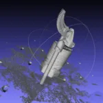
In 3D scanning, either a laser beam (“laser scan”) or a pattern (“structured light”) is projected onto the surface of the object. The resulting patterns on the object are captured by cameras and assembled into a 3D model using software and algorithms.
The advantages of this method are:
- No direct contact with the object is necessary.
- High measurement speed (especially with structured light).
- Free surfaces can be measured easily.
However, since the cameras project light onto the object’s surface, there are also two disadvantages:
- Surface properties: Depending on the material, light is reflected differently, which can lead to inaccuracies. Therefore, all objects should be coated with a matte layer (e.g., chalk spray). However, this may not be possible for some objects due to their material properties.
- Undercuts: Areas that cannot be fully illuminated cannot be captured by the cameras and are missing from the final model.
2. Computer Tomography (CT Scan)
In CT scanning, the object is scanned using X-rays. This process measures the outer and inner structures as well as the density of the object’s walls. The object rotates 360° during the process, creating numerous 2D images (“slices”), which are transformed into a 3D volume model using an algorithm. The advantages of this method are:
- Possible examination of surfaces and inaccessible areas (undercuts, cavities, etc.).
- Often, disassembly of the object can be avoided.
- Visibility of object parts in their function.
- Possibility of comparing the original and replica.
- Analysis of material condition (or fatigue).
However, CT scanners are very expensive and require a considerable amount of space (shielding from X-rays). In contrast, a 3D scanner often has the dimensions of a water boiler.
Direct Physical (Tactile) Measurements
In contrast to 3D scanning, direct physical measurements require direct contact with the object. Two basic approaches can be distinguished: 1. Measurements with a Coordinate Measuring Machine (CMM); 2. Manual measurements. In many cases, direct physical measurements are even more accurate than 3D scanning, but this depends to a large extent on the person performing the measurements and the instruments used.
1. Measurements with CMM (Coordinate Measuring Machine)
Coordinate Measuring Machines (CMMs) were originally not designed for creating 3D models but for dimension verification. Nevertheless, it is possible to generate a so-called point cloud from the acquired data. To make it usable for 3D printing, this point cloud is first converted into a surface model using algorithms and then into a volume model. This approach is particularly suitable for objects with simple geometry but requiring high accuracy.
2. Manual Measurements
In this method, the data from manual measurements are used to create a 3D model using CAD software. This process takes more time compared to a 3D scan, as the object needs to be measured, modeled, and verified.
For objects with simple geometries, such as components primarily consisting of basic geometric shapes, this method is often faster and more cost-effective. In contrast, 3D scanning requires a complex procedure to convert the data into volume models (surface reconstruction or volume reconstruction), whereas manual measurements create CAD data directly from the object.
From Point Cloud to STEP File

The following steps are necessary:
- Generate sufficient measurement data → Point cloud
- Convert to the .STL format (STereoLithography). → necessary for 3D printing
- Transform into the STandard for the Exchange of Product model data (STEP). → compatible with other CAx systems
In 3D scanning and tactile measurement, numerous measuring points are generated, and these are represented in a point cloud. However, this point cloud does not yet have surface properties. Algorithms recognize the connections between the measurement points and connect them (using vectors) into more complex geometric shapes, usually triangles or quadrilaterals. The result is mesh models, which are now almost infinitely manipulable and therefore crucial for the reverse engineering process. The mesh models are usually saved in the .STL file format, which can be directly used for 3D printing. To transfer the acquired data to other CAx systems, conversion to the Standard for the Exchange of Product Model Data (STEP) is necessary. This involves first performing surface reconstruction (exact/parametric), meaning defining, connecting, or summarizing the individual surfaces/regions. With the help of volume reconstruction, bodies are created from these surfaces, and they are saved in the formats .STEP, .STP, or .IGES. These formats allow the data to be transferred to most 3D systems.
Applications
Reverse engineering and 3D printing are often mentioned in the same breath. The techniques of reverse engineering are frequently used to obtain data for creating accurate 3D surface models. These models can be used, for example, to create a negative of the object for comparison with the original and to verify accuracy. Similarly, manipulated versions of the original can be 3D printed quickly and with high precision to quickly test the effects of the manipulations.
Further applications arise for the manufacture of casting molds. This can involve direct 3D printing of a casting mold or the production of tools specifically designed for the object.
If CT scanning is used for reverse engineering, complex internal structures of objects can also be measured (e.g., for analyzing material fatigue).
Summary
3D printing and its related technologies can make a significant contribution to reverse engineering. Particularly, 3D scanning technologies simplify the digitalization of objects, and with the help of 3D printing, (manipulated) models can be produced quickly and with high accuracy for comparison with the original object.
About 3Faktur: 3Faktur specializes in 3D printing, rapid prototyping, and rapid manufacturing. We utilize HP’s Multi Jet Fusion technology and offer various materials for prototyping and series production. If you have any questions about your project, feel free to contact us.
