In our series “Construction for Additive Manufacturing“, we dedicate the second chapter to the requirements for the dataset. For 3D printing, a 3D model (such as a CAD file) is generally required, and in the case of serial production, a technical drawing is additionally needed. You can find detailed information about formats and requirements for both file types in this chapter.

Chapter 2 – Dataset Requirements
2.1 CAD Data
2.1.1 Formats
Data for 3D printing is required in the form of 3D models that describe an object in all dimensions. There are two main file types for 3D modeling: CAD data and mesh data. In order to be effectively used for 3D printing, CAD data from CAD design software (e.g., SolidWorks, Autodesk Fusion360, or Inventor) needs to be converted into mesh data (STL). Mesh data can be envisioned as a network of triangles that represent the 3D model.
Typical file formats in industrial 3D printing include:
- STL: These are mesh files that can be exported from almost all commonly used programs. The object data is stored in the form of a grid (triangles as the basis). For mesh files, the resolution should not be chosen too low (~0.01 – 0.05 mm) to avoid loss of quality.
- 3MF: This is a specifically developed XML-based file format that carries all the information (significantly more than STL) for 3D printing and is intended to replace STL as the standard file format. The 3MF format facilitates the transfer of 3D data and reduces the error-proneness of 3D models.
- STEP: A STEP file is a 3D data format used in Computer-Aided Design (CAD) for storing and exchanging product development data. It contains both geometric and visual information and is particularly useful for transferring data between different CAD systems. The typical file extensions are .stp or .step.
For more information about 3D printing file formats, you can also visit the following pages:
- Overview of the Most Common File Formats in 3D Printing
- Difference between STL and STP
- The Importance of the STL File Format
2.1.2 Necessary Properties of 3D Models
When converting CAD data into a mesh format, such as STL, errors can occur. Minor inconsistencies can usually be corrected before printing using specialized software. However, significant problems can also arise due to various reasons:
- Design-related: Some designs contain features that are not achievable in 3D printing. Examples include non-closed surfaces or elements that theoretically have a distance of zero from each other instead of being correctly connected. In the first case, the element cannot be represented at all or only with errors, while in the second case, the elements remain separate from each other even after printing.
- Software-related: Different design programs generate STL data of varying quality, especially with free or niche software. In addition, certain operations, such as Boolean operations, can lead to mesh errors.
Below, individual requirements are presented.
Solids
Objects must consist of solids, not individual faces. Surfaces have a width of 0 and therefore cannot be produced. In solids, all surfaces are completely connected (“watertight”).
Common, industrial construction programs represent objects correctly almost without exception. However, programs that are mainly optimized for design, architecture or similar applications may have such problems.
Intersections of surfaces
If polygons or parts of surfaces overlap, errors can occur during file processing. These are often expressed by surface damage to the printed object, e.g. grooves or irregular elevations. The printing errors are caused by misinterpretations of the software that ‘translates’ the 3D model for 3D printing. Causal overlaps occur, for example, w.hen combining several elements into one object. Here you can find instructions (English) from Autodesk/Netfabb on how to eliminate the overlaps.
Polygon alignment
The polygons are subject to a distinction into inner and outer sides. This is necessary to correctly determine the volume of the object. During this determination of the inner and outer sides, it occasionally happens due to software errors that a surface is oriented incorrectly. The 3D print preparation programs now “try” to repair this error, which can lead to misinterpretations (disappearance of elements or generation of artifacts). Therefore it is advisable to check the correct orientation of the surfaces and to correct the detected errors. Here you will find short instructions on how to do this using the Netfabb program, among others.

2.1.3 Conversion & Resolution of STL Files
The resolution of the STL file is crucial for the print quality, as it determines how many polygons are used to represent the 3D model. STL files are exported from the design program in the final step. Here, the resolution is determined by additional options that vary from program to program.
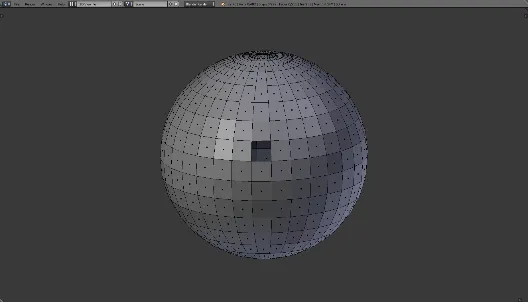
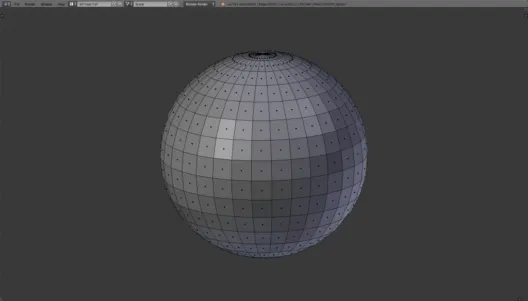
Too low a resolution will result in an angular surface with little detail. It is important to find a balance between resolution and file size, as excessive resolution will not improve things, but can result in large and difficult-to-handle files.
A handy rule is to scale the part on the screen to about 1:1. If angular surfaces are still visible, increase the resolution. If the surfaces appear smooth, the resolution is correct.
Example

File size: 0.01 MB

File size: 0.03 MB

File size: 0.5 MB

File size: 3.7 MB
2.2 Technical Drawing for Additive Manufacturing
In order to create the technical drawing optimally for 3D printing, please note the following:
Component alignment
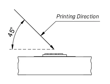
Specification: You can specify the jerk orientation (e.g. with arrows). Alternatively, you can mark the visible side of the part.
Background: The orientation has a significant influence on tolerances and surface quality at certain points of the part. Such an indication is particularly helpful for repeat production in order to increase replicability.
Channels
Specification: Channels in the component should be additionally marked.
Background: In some cases, it is not possible to remove residual powder from channels. Since these are sometimes difficult to recognize from the outside, a corresponding indication is very helpful.
Thread


Specification: Threads to be printed can, but do not have to be specified in the drawing. It is important that they are modeled in the STEP file. Threads that are specified in the drawing but not stored in STEP will not be produced.
If you wish to use threaded bushings, please state this explicitly when ordering or requesting a quotation.
Background: In machining production, it is common for only one core hole to be created in the STEP data. In additive manufacturing, on the other hand, production is based purely on the STEP data. If only one core hole is created, this is the only one that is manufactured. Threads are usually created in designs as textures or cylindrical surfaces. They are also transferred to the STL as surfaces by most programs. As a rule, this is recognized as an error by the printing software and the created hole is closed.
Tolerances
Specification: It should be noted that undersize and oversize are always the same in 3D printing. The ALlneral tolerances are material-dependent in the MJF process. For polyamide 12, for example, it is ± 0.3 mm or ± 0.3 % (from 100 mm).
The respective general tolerances can be found on the corresponding material pages (PA 12, PA 12 W, TPU, PA 11).
Background: Inaccuracies occur in the Multi-Jet Fusion process due to cooling and the associated material shrinkage or material stresses that arise. The effects occur ‘symmetrically’ in all directions.
Dimensions

Specification: For series production and desired initial sample inspection report, please specify all dimensions that are to be inspected.
Background:
- Measurability: In additive manufacturing, very complex components are often produced, which can only be measured with great effort. The specification of important measuring points therefore facilitates the inspection.
- Optimization: Specifying the inspection dimensions that are most important for the function of the component makes it easier to set the production parameters, since it is known to which dimensions production is to be optimized.
Surface

Specification: Expected values of surface roughness:
- Standard: Ra 4 – 6 µm bottom side / Ra 9 – 11 µm top side
- Vibratory finishing: Ra 3 – 5 µm bottom side / Ra 7 – 9 µm top side
- Vapor Smoothing (chemical smoothing): Ra 1 – 3 µm bottom side / Ra 3 – 6 µm top side
Background: The Multi Jet Fusion process is a powder-based process. The resulting surfaces are slightly rough. If the component is oriented diagonally during production, the surfaces are largely homogeneous, with roughness values between the above values for the top and bottom sides.
Painting
Specification:
- Color: please specify as RAL shade or Cerakote product number.
- For RAL please specify additionally (not necessary for Cerakote)
- Structure: desired lacquer structure
- Gloss level: e.g. high gloss, matt, silk matt
- Surfaces: Surfaces to be painted
- Paint mist: Surfaces with permissible or impermissible paint mist
