One of the outstanding strengths of 3D printing is the virtually unlimited design freedom it offers in the creation of objects. Despite this enormous flexibility, there are certain restrictions and requirements that must be taken into account to achieve optimal printing results. In this chapter, we have compiled the currently most important design requirements for you. They are essential for smoothly designing the 3D printing process and ensuring that the printed objects are represented correctly and of high quality.
Chapter 3: Basic Design Requirements
3.1 Wall Thickness
The Multi Jet Fusion process allows for the realization of very thin wall thicknesses. To ensure stable and reproducible results, we recommend not pushing the limits of feasibility in the design. The components need to be extensively processed after the printing process to remove excess powder. Especially thin walls break very easily during this process. It is therefore advisable to plan a certain safety margin for the wall thickness.


Polyamide 12
Multi Jet Fusion
- Minimum wall thickness:
- PA12, quality standard quality optimized; 0.5 mm (recommended 1.0 mm)
- PA12, quality standard cost optimized (“Economy”); 1.0 mm
- Note: If the component is to be as waterproof as possible, the wall thickness should be increased to a minimum of 2 mm.
- Recommended rib diameter:
- 1 mm, but we recommend 2 mm.
- Note: Production below 1 mm diameter is at your own risk.
TPU
Multi Jet Fusion
- Minimum wall thickness: 1 mm (in all directions).
- Recommended wall thickness: 1.5 mm (in all directions).
- Recommended rib diameter: 1 mm, but we recommend 2 mm.
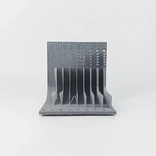
Printing Example Wall Thickness PA12
The sample component shows that very thin elements are not very stable. They can be damaged during printing or in subsequent post-processing. For a stable, replicable result, we recommend a minimum wall thickness of 1 mm.
3.2 Minimum & Maximum Object Size
The maximum build space size is 380 × 380 × 284 mm. For optimal results, we recommend designing the component in X & Y to be at least 10 mm smaller than the build space (i.e., max. 274 x 370 mm). In the Z direction, the full height can be used.
The resolution for very small components is not very good in the Multi Jet Fusion process. At least one dimension of the component should be >10 mm. For components with only a few millimeters in size, other additive manufacturing methods may be more suitable.
3.3 Font Sizes
Details, letters, characters, and logos can be realized in the form of embossing or engraving. Engravings have the advantage that thin elements are not as easily broken, so we generally recommend an engraving.
Engraving
- Minimum distance between two elements: 0.5 mm
- Depth of the engraving: min. 0.5 mm
Embossing
- Minimum structure width: 0.5 mm
- Height of the embossing: 0.5 – 1 mm

For embossing and engraving, we recommend a minimum element width of 0.5 mm. Thinner elements may break in embossing and may not be accurately represented in engravings (fusion of elements).
3.4. Holes & Channels
HOLES/OPENINGS
If you have depressions/holes in your object, make sure that the hole has a minimum diameter of 1 mm. For the depth, please consider the maximum of 5 – 7 cm.
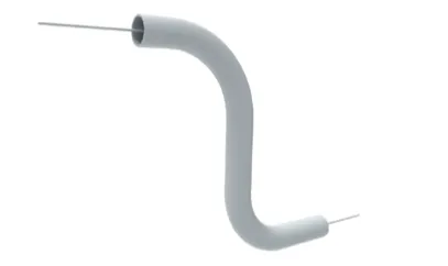
CHANNELS
Channels are indentations that are completely surrounded by material in an object and usually involve curves/direction changes. The material powder can be difficult to remove from the channels. A practical approach is to construct a thin object into the channel. This “wire” is then pulled out, and the remaining material can be removed from the channel. However, the angles and curves should not be too acute, as the object can easily tear (illustration). In this case, prior consultation is recommended.
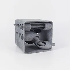
3.5. Voids
Voids from which excess material is to be removed require openings with a minimum diameter of 10 mm. The excess material is very firm and must be mechanically removed, so a sufficiently large opening is necessary.
For very large or difficult-to-reach areas, several openings should be provided.
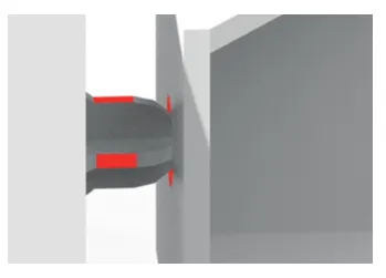
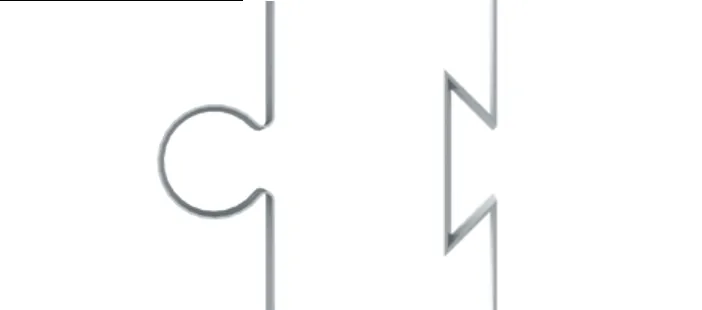
3.6 Joining Objects
Large objects can be divided and joined after 3D printing. This process can be supported by forward-looking design. Please plan for an approximate distance of 0.6 mm (geometry-dependent) for the interlocking components. To increase stability, you can provide adhesive structures (left illustration).
Please understand that joining is not part of our services. If you take on this process yourself, you can use cyanoacrylate or epoxy (possibly also polyurethane) based adhesives. Examples:
Low mechanical stress: Connecting PA12 together and to other surfaces (e.g., metal): Loctite 3D Printing Universal Bonder
High mechanical stress: e.g.
The above products are only examples; of course, you can use similar products from other manufacturers.
Source: HP
Source: HP
