In Chapter 3, the focus was on the basic design requirements for 3D printing. These are necessary for successful 3D printing and functional products. In addition, they can also incorporate functionalities into the 3D model, such as closures, threads, hinges, and movable elements. Some design guidelines must also be observed in this regard. This chapter deals with these aspects.
Chapter 4: Design Optimizations & Functional Elements
4.1 Movable Elements
Movable Elements: Movable elements require special design considerations. The minimum distance between the elements must be observed, which can vary depending on the wall thickness (recommendation: min. 0.7 mm). For wall thicknesses over 30 mm, larger distances between elements should be planned. For wall thicknesses of 3 mm, a distance of 0.3 mm is sufficient. The required distances depend heavily on the design of the respective components. Therefore, it is recommended to discuss your specific requirements with our engineers.
4.2 Hinges
Additive manufacturing methods offer interesting possibilities for designing hinges. Particularly, bending and film hinges have proven to be effective. Slight changes in wall thickness increase the flexibility of PA 12 parts. Typical wall thicknesses for hinges range between 0.3 and 0.8 mm.
However, the minimum wall thickness must also be considered to avoid breakage or destruction during cleaning. The wall thickness depends primarily on the length of the hinge. Polyamide 12 is largely isotropic, making the hinges stable and durable. Correct orientation during printing further enhances durability. The durability of a wide hinge can be further improved by dividing it into several narrower hinges. The narrow wall should be printed in the Z-direction, as it may be thinner in the X-Y direction.
4.3 Closures
4.3.1 General
Thermoplastic plastics are well-suited for manufacturing snap closures as they are flexible and stretchable. Depending on the design of the closure, these connections can also be resealable. When designing closures, material properties and the laws of physics must be considered. Various options are available for designing snap closures:
- Snap Arm: The snap arm has a thickening at the end, which is pressed into a corresponding opening. The durability of the connection depends on the chosen wall thicknesses. Variants of the snap arm closure include L-shaped and U-shaped snap arms.
- Spherical Snap Closure: This is a collective term for a variety of rotationally symmetric connection elements, where deformation occurs throughout the entire connection element during assembly. The mating part is inserted into a corresponding recess, thus connecting the two components.
- Rotating Snap Closure: The snap closure is opened using a rotating rod.
4.3.2 Design Guidelines
The strength of a snap closure connection is achieved through the wall thickness of the snap arm. The larger the force required to deflect the snap arm, the more robust/stronger the connection will be. The critical physical parameters are the bending stress and the cross-sectional moment of inertia of the closure components, as well as the elastic modulus of the material. Please observe the recommended closure force of 50 N to 100 N to allow the closure to be easily opened by hand.
Design guidelines for Multi Jet Fusion:
- Thickness of the snap arm: min. 1 mm
- Overhang depth: min. 1 mm
- Radius rounding at the base of the snap arm: 1/2 base thickness of the arm
- Round the corners of the overhang.
- Overhang chamfer angle: 35° to 40°
- Release angle: at 90°, the connection remains permanent; to open a snap closure, a release angle significantly below 90° is necessary.
- Also, consider the process-related tolerances when designing the components.
- Using a tapered snap arm reduces stress at the base, saves material, and reduces the closure force.
- For the protection of sensitive components, the use of a sintering box is recommended.
4.4 Threads
There are several ways to integrate threads into 3D-printed objects. The most common methods are direct 3D printing of the thread, tapping, and inserting threaded bushings. Here is a brief overview of the most common procedures.
Thread Inserts:
- Method: In the CAD dataset, only a core hole is designed. The necessary dimensions vary from manufacturer to manufacturer (follow manufacturer’s specifications for the thread inserts – e.g., here). After 3D printing, the thread insert is inserted into the core hole (spreading, hot pressing/ultrasonic welding, self-tapping).
- Recommendation: If the object geometry allows it, this method is the first choice and reliably creates even very small threads.
- Durability: The method ensures a high to very high durability.
- 3Faktur Service: We offer the integration of expansion threads for an additional fee.
Self-tapping screws:
- Method: Here, too, only the core hole is designed. After 3D printing, a self-tapping screw is screwed in once.
- Recommendation: A quick and practical solution for one-time assembly.
- Durability: For single use, durability is medium. If the assembly needs to be built and disassembled frequently, this method is not suitable.
Direct 3D printing of a thread:
- Method: The thread is designed in the CAD program and integrated into the component. Subsequently, the component is exported in the STEP or STL file format, as usual for 3D printing. (Source of error: If the thread is not displayed in the file, the export has failed.)
- Recommendation: Based on experience, this method is only suitable for metric threads starting from M6 x 0.7 (the manufacturer recommends M8).
- Durability: Due to the material properties, the durability of these threads is rather low.
Tapping threads:
- Method: First, a core hole is created in the CAD file. After 3D printing, the thread is cut into the core hole. If there are production-related deviations, additional reaming may be necessary.
- Recommendation: The accuracy in tapping is not optimal, so we do not recommend this method.
- Durability: Due to the material properties, the durability of these threads is rather low.
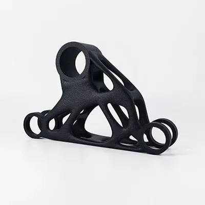
4.5 Lightweight Design / Topology Optimization
3D printing offers many options and savings potentials in the field of lightweight design/topology optimization. The peculiarities of additive manufacturing methods, in conjunction with the appropriate software, allow for the massive reduction of the number of parts in assemblies. Significant weight reductions in components are also easily achievable by omitting unnecessary/non-stressed elements. This process significantly reduces weight and costs.
Hollowing Objects
Solid components can be automatically hollowed out using suitable software. A minimum wall thickness of 2 mm is recommended. Thicker walls increase stability. When the cavity is freed from unused material powder, the weight of the component is reduced. If the unused material remains in the cavity, the stability of the component is increased, and post-processing time is reduced. Sufficient accessibility for depowdering must be ensured!
Lattice Structures
In this case, a solid component is also hollowed out, and a lattice structure is designed inside the cavity. This significantly improves the stability of the object while resulting in considerable weight reduction and cost savings due to increased process temperature, causing the powder inside the cavity to lightly sinter. This procedure contributes to further improving the stability of the final product.
Topology Optimization
The aim is to find and implement the best possible structure, shape, and interaction of elements. The goal is to adapt the design to achieve the desired functionality with the least possible use of material.
This usually results in a significant reduction in weight and, therefore, the price of the object. This is achieved by omitting non-stressed areas. Various commercial software programs are available for this purpose (e.g., Abaqus, Optistruct). Various methods are used: solid isotropic material penalization method, ground structure method, homogenization method, etc.
Structures larger than 10 mm are usually hollowed out. A typical wall thickness of 3 mm surrounds the resulting cavity. During the printing process, this cavity is filled with compressed powder. This powder is firmly anchored inside and cannot be “shaken out.”
Optionally, these structures can be equipped with a lattice, which increases stability and, due to the increased process temperature, causes the powder inside to sinter slightly. This approach additionally contributes to improving the stability of the final product.
“Classical” topology optimizations are mostly found in the field of metal 3D printing. Nevertheless, there are also applications in plastic 3D printing where this approach is useful. In addition to weight reduction, which is beneficial in areas such as automotive, robotics, aviation, or drones, the efficient use of resources contributes to increasing sustainability in 3D printing.
