In the previous Chapter 4, we focused on design guidelines for optimizing functions. In the following Chapter 5, the focus is on strategies to improve the surface quality of Multi Jet Fusion components. We will also provide design recommendations for typical post-processing methods.
Chapter 5: Surface Optimization
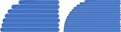
5.1 Top/Bottom Surfaces
A special feature of the Multi Jet Fusion process is that a heat-conductive fluid is sprayed onto the material powder. This leads to a slight reduction of the powder level. The heat source acts from above on the build area, causing the upward-facing surfaces to be heated more intensely and, consequently, become slightly rougher. On these surfaces, this leads to a slight sinking of the powder (“sinking”). On the edges, however, the opposite happens due to capillary effects: The mixture of fluid and powder is drawn slightly upwards. This results in slightly concave surfaces, i.e., the edges protrude up to about 0.1 mm. In contrast, the surfaces on the “bottom side” are smooth, but with slightly rounded edges towards the object. Consequently, visible surfaces should preferably be oriented downwards or at an angle. You can mark the visible side in your technical drawing or define the print orientation.

Source: HP

Source: HP
5.2 Stair-Step Effect
The so-called stair-step effect refers to the visible layers of the 3D printing process (for MJF 80 µm or 110 µm in “Economy” mode (only PA12)), which occur in the Z dimension. On straight surfaces, they are usually hardly or not visible at all. However, they can become visible, especially on curves and flat angles. To minimize the stair-step effect, objects protruding from a large flat surface should do so at an angle of at least 20°. On the bottom side, this effect is less pronounced, and an angle of at least 10° is sufficient.


5.3 Sinking/Warpage
Large/massive objects tend to experience sinking in the center. In contrast, thin, straight, relatively large surfaces may experience warping of the workpiece.
- Sinking: In the Multi Jet Fusion technology, massive structures can encounter problems such as sinking or the formation of an “elephant skin” (orange peel). This results from excessive heat absorption and uneven cooling. One solution strategy is to hollow out massive bodies, especially for structures with a thickness of 10 mm or more. To increase stability, support structures such as lattice grids (honeycomb or bone structures) can be integrated into these cavities. The choice of structure depends on the geometry and load direction. Escape holes can be inserted to remove excess powder. If cavities are closed, the powder remains inside. This option is available in our online tool, and by default, we will introduce a lattice grid structure.
- Warpage: Large, flat constructions in the Multi Jet Fusion process may tend to warp. This is due to the temperature difference that occurs when the outer areas in the build space cool down faster than the inner ones. This can lead to material stresses that cause the object to warp. Therefore, it is advisable to avoid such surfaces if functionally possible. One way to minimize warpage is to increase the wall thickness. However, additional “ribs” on the surface should be avoided as they retain heat and promote uneven cooling, which can favor warpage.
5.4 Design Recommendations for Post-Processing Methods in 3D Printing
Post-processing plays a key role in achieving the optimal end result in additive manufacturing. Depending on the 3D printing process, different procedures can be applied. It is important to note that post-processing can have additional design requirements. Our experts will be happy to advise you on the appropriate processes for your project.
5.4.1 Dyeing
In coloring, components are exposed to temperatures around 95°C (standard black coloring) or above 100°C (deep dye coloring) and immersed in a coloring solution. This controlled reaction causes the components to absorb pigments, which colors them.
Design information
- Warpage: Components with a length-to-height ratio of 10:1 or more are unsuitable for the dyeing process, as high temperatures and solvents can increase warpage.Wall Thicknesses:
- Wall thickness can affect the final result when coloring white components. Thin walls (< 1 mm) may be somewhat translucent, making colors appear lighter. For uniform coloring, all wall thicknesses should be the same, otherwise a minimum wall thickness of 1 mm should be maintained on the visible side.
More information:
5.4.2 Painting
Painting involves the application of one or more layers, usually acrylic-based plastics, containing pigments and possibly other substances. These additives can affect the structure and create special effects, such as metallic paint finishes.
Design notes for painting:
- Details: avoid fine details, as they can become clogged during painting and are subsequently no longer visible.
- Accessibility: areas that are difficult to reach may be painted unevenly, resulting in inhomogeneous surfaces and varying film thicknesses.
- Shaping: Use curves instead of sharp edges, as paint can run off edges and create thinner layers. This can affect the homogeneity and stability of the paint finish.
- Surface texture: A uniform, wide surface leads to a better paint finish. The more elements, elevations or depressions there are, the more uneven the result may be.
- Surface quality: Since the paint layer is usually too thin to conceal uneven surfaces, you should aim for optimum surface quality. Chemical smoothing as a pretreatment may be recommended.
- Warpage: Painting can be problematic for components that exhibit a high risk of warpage. This is due in part to the polymerization of the paint layers, which themselves can exhibit shrinkage and thus deform thin wall thicknesses.
More information:
Shot Peening
Shot peening is a surface finishing process in which small particles or “shots” are fired at high velocity onto the surface of the component. This process is used to solidify the initially porous surface to produce more homogeneous and resistant surfaces. Unless chemical smoothing is requested, we process all colored components at 3Faktur using this technology – no separate order is required.
Construction Notes:
- Wall Thicknesses: A minimum wall thickness of 1.0 mm is recommended, as the process places a high mechanical load on the components. Wall thicknesses that are too thin can be damaged (“shot through”) by the processing and pointed edges can break out.
- Accessibility: The more accessible the elements are, the more uniform and effective the machining is, which leads to a better end result in the form of a homogeneous surface.
- Narrow openings: Machining media can get stuck in narrow slots and cannot be removed. We therefore recommend designing openings with a minimum width of 1 mm.
More information:
5.4.4 Vapor Smoothing (Chemical Smoothing)
In the process of chemical smoothing, the components to be treated are brought into contact with vaporized solvent in a closed chamber. This condenses on the surface and liquefies it briefly, which is equivalent to “melting” the often rough surfaces of 3D-printed components. By softening the surface, pores are sealed and small irregularities are eliminated. The end result is a virtually pore-free, smooth surface.
Design notes for chemical smoothing:
- Wall thicknesses:
Thin walls: for walls less than 1 mm thick, it is difficult to create a temperature gradient. As a result, little or no solvent condenses, resulting in a less pronounced effect. We therefore recommend a minimum wall thickness of 1 mm.
Different wall thicknesses: Parts with significant differences in wall thickness may have inhomogeneous surfaces, as more solvent condenses on solid elements than on thinner ones. Avoid large variations in wall thickness in the visible area. - Accessibility: This process works best on easily accessible areas. Solvent penetrates difficultly into undercuts or cavities, resulting in minimal or no machining in these areas.
- Edges: Sharp internal edges should be avoided as solvent can accumulate here and cause surface damage similar to welds.
- Positioning in the build space: There are two options for placing components in the build space.
Lay-up: The parts are placed on a nail board. This method is less expensive, but affects the bottom of the part. Temporary support elements can be added if needed and removed after machining. Unless otherwise selected, we will use this positioning method.
Suspension: The part is suspended in the build space. This results in a more uniform treatment, with a mark visible at the point of suspension. Again, you can provide structures where the part is suspended and removed after machining.
More information
5.5 General Notes
- Use smooth transitions between different cross sections.
- Hollowing can only be done by us, unless the cavity has an opening.
- Avoid structures with aspect ratios greater than 10:1.
- Refrain from using elevations and ribs on large, flat surfaces.
- Apply details to the underside of large surfaces.
- Be aware of finishing procedures that are necessary for your product. These may change the design requirements.
