Image: Shutterstock / Gorodenkoff
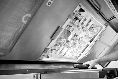
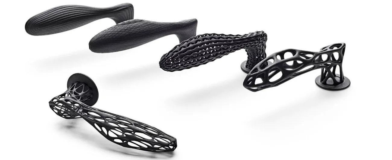
For additive manufacturing of plastic parts, there is less restriction in the design than for most conventional processes, such as injection molding. In particular, this is true for powder bed-based 3D printing processes (eg. Multi Jet Fusion), where (almost) any design is possible.
Plastic components that have been designed and optimized for injection molding or metal-cutting processes can usually also be produced using the Multi Jet Fusion process. However, it is advisable, especially for larger quantities, to optimize them for 3D printing (design for additive manufacturing – DFAM).
On this page we have compiled some recommendations for the design of additively manufactured components parts on this page:
1. 3D file requirements

Basic requirements for the 3D digital model, or CAD file, without which a part cannot be processed for 3D printing. This concerns the way the 3D model is set-up, not the design.
2. printability & design guidelines.

This concerns the design of the components, i.e. the properties that are mandatory for successful production. Examples include minimum wall thicknesses, channels/holes, and cavity requirements.
3. design optimization for 3D printing

In this section, we provide guidance on optimization for additive manufacturing in terms of function (holes/threads, topology optimization, etc.) and cost effectiveness (cost savings).

Image: Shutterstock / Fernando Blanco Calzada
1. 3D file requirements
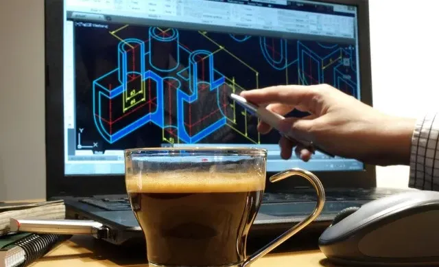
3D printing requires the object to be printed as a digital model. Models are created using CAD, or 3D design programs, or through a 3D scan.
With common design programs, such as. Inventor, Fusion360 or Solidworks, the model can usually be exported without problems into standard formats such as STEP or STL. A check (with the exception of the file format) is usually not necessary.
For older software versions, less common design programs3D programs in the design or architecture as well as 3D scan we recommend that you follow the requirements listed here.
For the color 3D printing the respective texture or certain color information is required in addition to the 3D model. The file formats OBJ, 3MF or VRML can do this.
In addition to the requirements, you will also find links to instructions with suggested solutions:
File formats
For 3D printing, data in the form of 3D models is required. The following formats ure mostly used:
- STEPCAD format, which can be exported from all common CAD programs. More rarely, the obsolete IGES format is also used, which contains similar information.
- STL, OBJ: Mesh files, which can also be exported from almost all common programs. With mesh files you have to take care that the resolution is not too low (~0.01 – 0.05 mm), otherwise the quality can be reduced (here you can find examples). If you are unsure about the resolution, feel free to send us the STEP datasets.
- 3MF, VRML, OBJ: File formats that contain color information/textures and are needed for color 3D printing.
Please note: Unfortunately, it is not possible to 3D print or quote based on images, drawings and from photos.
For more information about 3D printing file formats, please visit the following pages:
Waterproof
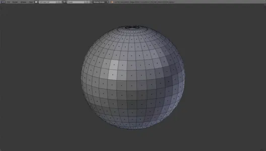
A basic requirement for 3D printing is that the object to be printed is a solid. This solid must be completely closed i.e. there must not be any holes (e.g. missing polygons).
You can imagine it figuratively like this: You try to fill the object with water -> would it run out somewhere?
The problem of missing polygons can occur ‘accidentally’ in some programs during some (conversion) operations, e.g. Boolean operations.
Minor errors are corrected by us immediately. However, larger errors/gaps in the interface can lead to misinterpretations, since it is no longer clear to the printer software what is to be printed at this point. This error manifests itself in the fact that parts of the object can disappear or ‘bulges’ are printed on the object.
Ways to check the watertightness of your 3D model:
- Blender: With the free 3D program Blender you can check if your 3D model is waterproof, for this you can use the tool ‘Solid Check‘ in the 3D printing toolbox.
- Meshmixer: Instructions how to use (the also free program) Meshmixer to check your 3D model for watertightness can be found here (external links): Instruction1; tutorial2; instruction3;

Not waterproof 3D model due to missing polygons.

Waterproof 3D model.
Solid
3D models consisting only of surfaces cannot be printed, this is mostly the case with models constructed for visualization purposes. Such 3D models can often be found on 3D databases on the Internet.
The problem with these surfaces is that they have a wall thickness of 0. However, 3D printing basically requires solids, which means that the object walls must have a wall thickness > 0. In addition, you need to consider the minimum wall thicknesses when creating the 3D models, because walls that are too thin run the risk of breaking.
For HP Multi Jet Fusion, you can use the following dimensions as a guide:
- min. 0.5 mm (object is somewhat flexible)
- 2 mm (object is quite stable/rigid)
- min. 0.9 mm for unsupported objects/object parts
Overlapping of surfaces
Another source of errors in 3D printing, the cause of which lies in the 3D models, are overlaps (self-intersection) of polygons of the objects to be printed. Overlaps happen when two objects occupy the same position in the 3D model. Often this leads to misinterpretation of the 3D printing program and the 3D print becomes faulty.
This can happen when creating the 3D model if you combine/group two independent bodies. Grouping alone is not enough for 3D printing to be error-free. Boolean operations can be used to combine these bodies into one object, thus largely eliminating misinterpretation.
Here you can find a tutorial (English) from Autodesk/Netfabb on how to eliminate the overlaps.
Alignment of the surfaces
The polygons are subject to a distinction into inner and outer faces. This is necessary to correctly determine the volume of the object. During this determination of the inner and outer sides, it happens from time to time due to software errors that a surface is oriented incorrectly.
The 3D print preparation programs now “try” to repair this error, which can lead to misinterpretations (disappearance of elements or generation of artifacts). Therefore, it is advisable to check the correct orientation of the surfaces and correct the detected errors.
Here you will find short instructions on how to do this using the Netfabb program, among others.

Image: 3Faktur
2. printability & design guidelines
The basic requirements for additive manufacturing with the with the Multi Jet Fusion process are manageable. In particular, wall thicknesses, channels and correct dimensioning must be taken into account.
Once these requirements are met, the object can be manufactured. To further optimize the result, please also note the information in point 3 (Optimizing the design for 3D printing).
Minimum wall thicknesses
In 3D printing, a wall thickness is the thickness of a structure of the part. Different types of walls are distinguished. The wall thicknesses can be checked with the Meshmixer program (area: Analysis -> option: Thickness or Measure), among others.
Walls in a narrower sense:
- Supported (connected) wallsAre connected to other structures on at least two sides.
- Unsupported (free standing) walls: Are connected to other structures on one side only.
Walkways: These are characterized by a smaller surface area and are usually square, round or oval objects. They are more similar to bars than walls. But the same problems occur with them as with “classic” walls. Due to their small width, they are much more fragile than walls.
- Supported bars: These are bars that are connected to other structures in two places.
- Unsupported bars: Are connected to the rest of the structure in one place only.
Effects of insufficient wall thickness
- Warpage: Due to the process, warpage can occur in relatively thin, large-area walls (more on this in section 3 – Design optimization). Since the material also has some flexibility, the risk is amplified. Therefore, critical walls should be supported or provided with increased wall thickness.
- Fracture: Walls that are too thin can crack/break even during the printing process. But breakage can also occur during reworking and finishing. Two work steps in particular are critical here:
- Getting the workpiece out of the powder bed: The dead weight of the remaining powder alone can cause parts to break off. However, the obscuring of filigree structures by the material powder can also cause components of the workpiece to break off when it is removed from the powder bed or when the powder is removed by the production worker. In this case, unsupported and filigree structures are particularly susceptible to breakage.
- Cleaning: A sandblasting process is used to clean the workpieces. In this process, high kinetic energy is used to blow the blasting material onto the object. This energy is sufficient to penetrate very thin walls (< 0.3 mm) of the object. Even the breaking off of unsupported structures is possible during sandblasting. Even distortion is possible, due to the sometimes very high temperatures caused by the resulting friction, in very thin areas

Example: supported wall

Example: unsupported wall

Example: supported web

Example: unsupported web
Guide values for wall thicknesses
The minimum wall thickness for the Multi Jet Fusion process is 0.7 mm. This should keep you on the safe side in most cases, however this is the lower limit, if you want to be safe you should design the walls a little thicker. Following are a few rules for designing for plastic 3D printing:
- The larger the surface the stronger it should be! For small walls up to a few mm (rule of thumb 10 mm for unsupported, 25 mm for supported walls) 0.7 mm is sufficient. For larger walls, the stability is reduced. Unfortunately, it is not possible to make any binding statements as to which sizes and to what extent this occurs. The following values have proven to be practicable:
- For walls with a few cm to ~ 10 cm ⇒ 1 – 2 mm.
- For walls with 10 cm – 20 cm ⇒ 2.0 – 2.5 mm.
- For walls with 20 cm – 30 cm ⇒ 2.5 – 3.0 mm.
- For walls > 30 cm ⇒ >3.0 mm.
- Unsupported walls should generally be stronger than supported ones. But again, there are no absolute values, since stability also depends to a large extent on the geometry of the structures.
Voids and Escape Holes
Escape Holes:
“3D printing also allows you to hollow out the objects, this saves material, weight and cost. However, with powder bed-based 3D printing processes, material powder still remains in the cavities. In order to remove this powder, so-called “”escape holes must be integrated into the 3D model.
Notes on the creation of
escape holes
:
Simple geometries
of the cavity, without twists and curves: often one opening is sufficient to blow the excess material out of the cavity. Openings of min. 5 mm are necessary.
More complex geometries
of the cavity or relatively large cavity: here, min. two openings are usually required, so that the compressed air can enter on one side and the powder can exit through the second hole. These holes can also be smaller than 5 mm.
”
Hints for creating Escape Holes:
- Simple geometries of the cavity, without twists and curves: often one opening is sufficient to blow the excess material out of the cavity. Openings of min. 5 mm are necessary.
- More complex geometries of the cavity or relatively large cavity: here, min. two openings are usually required, so that the compressed air can enter on one side and the powder can exit through the second hole. These holes can also be smaller than 5 mm.
- Hint: In the case of a complex geometry of the cavity or with openings < 5 mm (Minimum requirement 2 mm diameter), the powder may collect in corners, at angles or at curves and cannot be removed. This can lead to malfunction of the component over time, due to drying or vibration can be released.
Design recommendations:
- One opening: min. 5 mm diameter
- Two or more holes: 5 mm diameter recommended, minimum 2 mm diameter
Channels and blind holes
A channel is a recess in an otherwise solid structure that has an entrance and an exit, effectively a tube. Additive manufacturing with powder bed-based 3D printing processes allows you to directly print channels or blind holes (only one opening).
Problem situation:
When channels or blind holes are printed directly, the problem often arises that the material powder that is not needed must also be removed from the channel. This can be difficult with curved or angled channels, since the air jet for discharging the material does not reach the entire channel. Or, the material may collect at the bends and clog the duct.
Solutions:
For straight blind holes or ducts, simple re-drilling is possible, which usually removes the excess material reliably. However, it is important to maintain a minimum diameter of 2 mm.
For curved channels, the diameter should be as large as possible. Another possibility is to construct a kind of of wire or chain into the duct.. This element is pulled out during cleaning, thus loosening and removing a large part of the “filling material” inside the duct. The remaining material can then be more easily removed from the duct.
The wire should have a minimum diameter of 1 mm and a and a distance of at least 0.5 mm from the duct wall. more for larger channels.

Auxiliary design for 3D printing of channels for Multi Jet Fusion. Illustration: HP.
Scale and unit of the object
Different 3D programs work with different units. In Germany, mm is predominantly used, but cm and, mostly in Anglo-Saxon programs, inches are also possible. In the architectural field, m is also often used. An STP file contains the corresponding unit of measurement, so that (mostly) a confusion can be excluded. In the case of mesh files, such as the STL format, this this information is not included.
Problem situation:
We are recurrently dealing with confusion in the units of measurement. Mostly between cm and mm sometimes also between mm and inch (inch). Errors also frequently occur in scaling, especially with scaled-down models of large components or systems.
In case of an unclear specification, we always assume the standard unit mm. As long as the objects do not slip into an area where they are no longer printable due to the confusion, we do not notice the incorrect scaling or unit.
Suggested solutions:
- Quotations: Our quotes include the dimensions of the object, we ask that you always check them.
- Direct order: For a direct order, the dimensions are visible in the order field.
- General: In case of doubt, you can simply specify the dimensions of the objects in the comment field (order through our system), or by e-mail or on your order form.
Direct order

The dimensions are available at our Online 3D Printing Service directly below the object representation.
E-Mail offer

In our e-mail offers you will find the dimensions in the object description.
Fonts & engravings
Markings or characters on the 3D-printed object are also possible, however, certain design specifications must be adhered to here as well. Otherwise, object components may merge or break off. For the readability of 3D-printed fonts, you should also take the design instructions to heart.
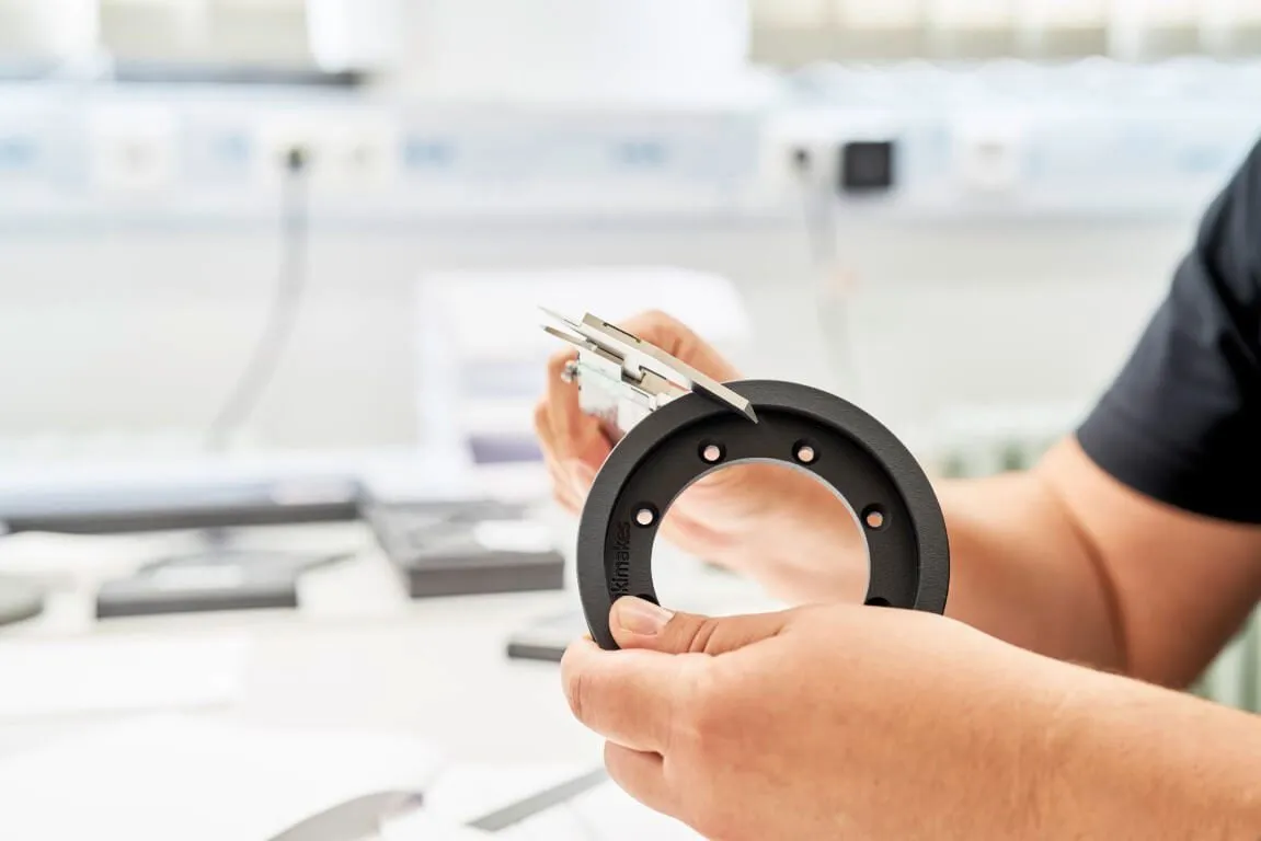
- Min. font size for indentations/elevations: 6 pt
- Min. diameter of holes with 1 mm wall thickness: 0.5 mm
- Min. diameter of a stem 10 mm high: 0.5 mm
- Min. distance between two walls: 0.5 mm
- Optimal depth of a font: 1 mm
- Optimal height of a font: 1 mm

Source: Design Guideline HP

Source: Design Guideline HP
Design guidelines for merging objects
You can also design 3D models so that the models will be tightly joined together later. This is useful for very large objects that are too big for a build space. The same applies to objects that are to be joined together during 3D printing. You should observe the following design notes.
- Min. distance between objects: 0.4 mm
- Also note a general tolerance of ± 0.3 mm
- For objects printed together: min. 0.7 mm
- From wall thicknesses of > 50 mm: slightly more
Bonding PA 12 components together
- Adhesive structures increase effect (see figure)
- Before: Clean surfaces
- Optional: mechanical abrasion (better bonding effect)
- Possible adhesives: epoxy adhesive, 2-component adhesive (polyurethane), acrylic adhesive, cyanoacrylate adhesive (for small surfaces)
- Important: Observe the safety instructions for the individual adhesives!

Example of joining, source: HP

Minimum distance of objects printed together, source: HP

Examples of adhesive structures, source: HP

Image: iStock / Latsalomao
3. Design optimization for 3D printing
If all the requirements in sections 1 and 2 are met, the object can be printed. However, this does not always lead to the desired result.
In this section, you will find tips on how to optimize the design can be optimized for 3D printing in terms of function or cost. costs.
Especially in case of higher quantities or the use of the part as a functional part, it is recommended to check or adapt the model accordingly.
3.1 Functionality
Warpage, warping & sagging
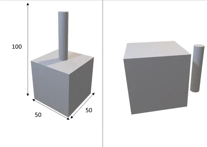
Large / massive bodies tend to sink in at the center. cave in. Thin, straight, relatively large surfaces, on the other hand, can cause warping of the workpiece. warping of the workpiece occur.
Problem situation:
- Shrinkage: Large / massive solids can sink in during the Multi Jet Fusion 3D printing process or exhibit an elephant skin (orange peel) on the surface. Due to the geometry and the process, massive solids absorb a great deal of heat and radiate it to the surrounding powder. This can cause the surrounding material to be melted as well, resulting in unclean edges. Another problem with solid solids is that they cool unevenly due to their shape. This uneven cooling can cause deviations or sagging.
”
- Warpage: Large-scale, thin structures tend to warp. Here, too, temperature plays the decisive role: the structures cool down very quickly, but faster on the outside (in the build space) than on the inside. As a result, material stresses can occur, which can lead to warping or “”warping of the object lead.
”
Solution approaches:
- Solid solids: Solid bodies can be hollowed out if this is compatible with the statics. This is recommended for structures with a thickness of 20 mm or more. It is also possible to insert support structures for cavities that increase stability. Depending on the geometry and direction of the load, various structures may be appropriate (grids, honeycombs, bone structures, trusses, bamboo). They can be Escape Holes (see Section 2 – Design guidelines) or omit them. In the latter case, the powder remains in the interior. In such a case, however, you should in any case explicitly point this out to usOtherwise, completely enclosed cavities will be automatically closed in the print preparation.
- Large-area, thin structures: In the case of such structures, we try to limit warpage as far as technically possible by means of optimum positioning in the printing chamber and extended cooling phases. Unfortunately, this cannot be completely ruled out.
As a general rule, such surfaces should be avoided. It is recommended to increase the wall thickness as much as possible.
Stability of the elements
Stability of the workpieces:
Since the advent of 3D printing, there has been a belief that everything is now 3D printable. For geometric shapes, this is true to some extent. However, 3D-printed structures must also support themselves and be stable. In other words – the laws of physics also apply to 3D printing.
Problem situation:
Based on the 3D model, it is not always possible to clearly see whether the object is stable after 3D printing. If filigree structures have to support a larger block of material on their own, the structure can easily break off. If the walls are too thin, sometimes the structure’s own weight is enough to cause it to break off.

Make sure load-bearing elements can withstand the load.
Design Considerations:
Verify that load-bearing structures can withstand the load. In most cases, CAD programs have the ability to check the stability of individual elements and, if necessary, reinforce critical elements or insert additional structures.
Corners, edges, radii
Corners and edges are usually rounded during printing. Very sharp edges can also break out.
Problem situation:
Flat edges tapering to 0 fall below the minimum wall thickness requirement. This can cause edges to break out during printing or finishing.
Design Notes:
Avoid too acute angles in design, or plan with rounded edges right away. By cleverly orienting the object in the build space, you can still get something out of it in terms of “sharpness”. The minimum recommended radius is 0.4 mm..
Topology optimization
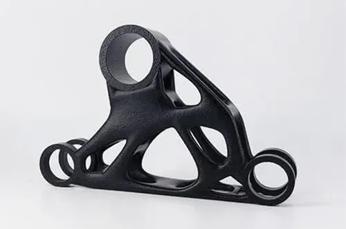
With the topology optimization is about finding and implementing the best possible structure, shape and interaction of the elements. The aim is to adapt the design in such a way that the desired functionality is achieved with the least possible use of materials.
This usually manifests itself in a significant reduction in the weight and thus the price of the object. The reason for this is the omission of superfluous (non-loaded) surfaces. Various commercial software programs are available for this purpose (e.g. Abaqus, Optistruct). Different methods are applied: solid isotropic material penalization method (SIMP), ground structure method, homogenization method, etc.

Source: Siemens PLM Software
Drillings
Bohrungen are an important part of many components. Here the question arises whether these should be added later or printed right away. It always happens that hole punches are not quite straight or that the 3D-printed holes are closed.
When directly 3D printing holes, it depends on the direction in which they are printed in the component.
- Holes that are horizontal in the build space tend to be oval due to the manufacturing process.
- Vertical holes are usually very accurate (within the limits set by the technical framework). technical conditions given).
In 3D printing, it therefore makes a noticeable difference, in which direction curves are 3D printed. are 3D printed. If the curves are oriented on the XY axis, they will usually be very accurate and round. On the Z axis, on the other hand, the layers of the printing process become visible due to the production process (to varying degrees depending on the radius), so that perfect curves are not produced.
The orientation of a part in the 3D printer build space is variable; if necessary, point out important curves so that we can orient the part accordingly. Let knowledge of the constraints of the curves be incorporated into the design of the 3D model to get the best results.
To avoid plugging of the holes please make sure that the diameter of the hole is large enough (diameter > 0.5 mm). In the case of very deep holes, there is also the fact that the walls of the hole give off heat and thus more material is melted together than intended. You can re-drill these holes manually. Another possibility is to include these conditions in the design, but this requires some testing and experience. Very deep holes will narrow somewhat toward the end due to heat absorption of the material powder.
Gewinde
Threads are functionally very important elements in components. Threads can be realized in three ways in the Multi Jet Fusion process.
Direct pressure of the threads
From a thread size of M4, but better from M6, threads can be printed directly. However, stability is limited, especially for smaller sizes (M4 – M8).
For large or very large threads, e.g. M10 or larger direct printing is a practical alternative with good stability.
Re-tapping of threads
The material PA12 has a low porosity in the Multi Jet Fusion process. The printing of a core hole with subsequent recutting of the thread is therefore a target-oriented method.
It should be noted, however, that PA12 is rather soft. Therefore, recut threads are also not suitable for high loads or for a high number of screw cycles.
Thread inserts
Thread inserts are the method of choice when threads with high load capacity are required. As with thread cutting, the core hole can also be printed directly here, so that subsequent use of the bushings is simplified.
In addition to “classic” thread inserts Helicoils can also be used. The load capacity is somewhat lower than with conventional inserts, but the assembly effort is very low.
Hinges and living hinges
Due to the flexibility of polyamide 12, film or bending hinges can be produced using the Multi Jet Fusion process. The wall thickness should be between 0.5 and 1.5 mm depending on the length of the hinge.
The polyamide 12 material produced is largely isotropic, consequently the hinges are stable and have a long service life.
3.2 Cost reduction
Volume reduction
The main price factors in the MJF process are the material input and the space occupied in the machine (“machine volume” – see next point).
The following strategies can be used to reduce material volume:
- Removal of superfluous elements: Structures that are not absolutely necessary can be removed. Often plastic parts are designed for casting or machining processes and contain surfaces that are not required for 3D printing. The geometries with a high degree of complexity, such as undercuts or free surfaces, which are created by removing these surfaces, can be implemented with 3D printing without any problems.
- Hollowing out solid structures: From a wall thickness of 20 mm, we recommend hollowing out the model. You have the following options:
- Hollowing out with an opening (“Escape Hole” – see section 2). Excess material is removed from the cavity.
- Hollowing without opening: excess material remains in the cavity.
- Hollowing out with grid structure: material remains in the interior, and support structures are also drawn in to give the interior additional stability. The grid structure can be inserted by us at your request.
- Topology optimization: See previous section (3.1)
Reduction of machine volume
The installation space in the Multi Jet Fusion process can be completely filled with components. Typically, this is between 50 and 250 parts.
The bulkier a component is, the more space it takes up. Unused space is expensive, so the price of the component increases accordingly.
In order to reduce the price, it is advisable to use bulky structuresif possible, either remove them altogether removedor print them print them separately.
Assembling complex assemblies into a single part
3D printing offers the possibility to reduce number of components required in an assembly. This can save both weight and cost. This is done by fusing adjacent components together. However, this is only possible if the components can be made from the same material and they are not intended to be independently movable or individually removable. This process reduces the number of components in an assembly and consequently significantly reduces manufacturing costs.

About 3Faktur: 3Faktur is a 3D printing service provider. We are specialists in 3D printing of plastic objects for rapid prototyping (low volume) and small batch additive manufacturing (rapid manufacturing). Contact us.